


LA17000M LC75410E/WLC75410E/WLA17000M
1
FM
ANTD
ANT
D
2
FM RF
AGC
3
FE
GND
4
FM
OSC
5 6
AM/FM
SW
7
AM
OSC
8
NC
Sens
9
NC
AGC
10
AM
OSC
11
Gore
OUT
12 13
MPX
Pdot IN
14
NC MPX
GND
15 16 17
SD
ST-IND
18
PLL IN
19 20
PD1
41
AM/FM
S-METER
4243
MRC
OUT
44
SNCHCCNC
454647
DET
OUT
SEP
ADJ
48
FM
S-METER
49
MUTE
DRIVE
50
AFC
IN
51
QD
OUT
52
QD
IN
53
V
REF
54
FM
SD
55
KEYED
AGC
56
V
CC
57
C.
HCC
58
AM
LC
59
PILOT
DET
60
IF
AGC
21
PLL
V
SS
22
PDS
23
XBUFF
24
I/O-2
25
X' IN
26
X' OUT
27
CE
28
DI
29
CL
30
DO
31
I/O-1
32
HCTR
33
SEEKSW
34
35
36
37
MPX VCO
38
IF COUNT BUFF
SEEK/STOP Switch
CSB912TF108
39
GND
40
PHASE
COMP
61
AM DET
62
AM ANTD
WIDE AGC
63
FM MUTE
ON ADJ
64
RF AGC
65
2nd MIX IN
66
FM IF BYPASS
VSM
SHIFTER
67
FM IF
IN
68
69
1st IF OUT
70
AM MIX OUT
71
AM SD ADJ
WIDE AGC IN
72
1st IF IN
73
AM RF AGC OUT
74
75
N-AGC IN
MUTE ATT ADJ
76
MIX OUT
77
FE V
CC
78
1st IF
Narrow IN
79
AM 1st
MIX IN
80
FM
MIX IN
3.3
µ
F
0.022
µ
F
0.022
µ
F
0.01
µ
F
0.47
µ
F
1
µ
F
0.01
µ
F
0.022
µ
F
0.015
µ
F
6800pF 0.01
µ
F
30k
Ω
1M
Ω
350
Ω
51k
Ω
30k
Ω
10k
Ω
22k
Ω
51k
Ω
10k
Ω
11k
Ω
300
Ω
51k
Ω
470
Ω
100k
Ω
510
Ω
33
Ω
10k
Ω
10k
Ω
24k
Ω
30k
Ω
12k
Ω
62k
Ω
82k
Ω
560
Ω
56k
Ω
33k
Ω
33k
Ω
1000pF
10k
Ω
50k
Ω
5.6k
Ω
47k
Ω
47k
Ω
47k
Ω
100k
Ω
100k
Ω
51k
Ω
5V
10k
Ω
100k
Ω
10k
Ω
10pF
300pF
150pF
100pF
30pF
V
CC
=8V
FM ANT IN
5pF
AGC
HPH
HOLE
DET
F.F.19k
90
PHASE
COMP.
VCO
PILOT
DET.
CCB
I/F
POWER
ON
RESET
PHASE
DETECTOR
CHARGE
PUMP
F.F.19k
90
F.F.30k
0
F.F.
PILOT
CAN.
UNTVERSAL
COUNTER
DATA SHIFT REGISTER
LATCH
12Bits
PROGRAMMABLE
DIVIDER
SWALLOW
COUNTER
1/16,1/17 4Bits
REFERENCE
DIVIDER
TRIG
HCC
SNC
VCO
STOP
OC-C
DET
AFC
CI AMP
LPF
TRIG GATE
+—
MIX
MIX
ANT
D
OSC
BUFF
OSC
Q.DET
MUTE
AMP.
MUTE
DRIVE
DET
IF
AGC
L.C.
BUFF
OSC
BUFF
AM
1ST
OSC
BUFF
IF LIMIT
AMP.
Keyed
AGC
MAIN
HC
SUB
DEC
MAT
RIX
F.E
REG
FM/AM
SWITCH
AM/FM
V
REF
CF
SW
W.B AGC
RF AGC
AM SM
AM SD
FM SM
FM SD
IF BUFFER
MRC
RF AGC
WB AGC
TWEET
+
+
+
+
+
+
+
+
+
+
+
+
+
+
+
+
0.015
µ
F
0.22
µ
F
3.3
µ
F
15pF
15pF
0.022
µ
F
0.022
µ
F
100
µ
H
100
µ
H
0.022
µ
F
0.022
µ
F
47
µ
F
FC18
100
µ
H
1MH
0.022
µ
F
1
µ
F
0.022
µ
F
100
µ
F
+
2.2
µ
F
0.47
µ
F
1
µ
F
10
µ
F
0.22
µ
F
2200pF
0.1
µ
F
0.47
µ
F
0.01
µ
F
0.22
µ
F
1
µ
F
1
µ
F
0.22
µ
F
1
µ
F
0.47
µ
F
0.01
µ
F
0.022
µ
F
Pdot C
ADJ
100pF
5V
24pF
24pF
10.25
MHz
PLL V
DD
=5V
FM BF GND
L-CHCF SW R-CH FMIF AMNC
MPX V
CC
FM/AM
VT
FMIF AM
GND
SEEK AM/FM SD
STOP FM ST IND
SDSTSW
I/O-1
To
micro
controller
MUTE
OFF(RDS)
AM
(STEFEO)
IF OUT
MRC
SENOR
AUTO ADJ
+
30
Ω
200k
Ω
100
Ω
100k
Ω
100k
Ω
220
Ω
30k
Ω
15
Ω
30
Ω
100k
Ω
150
Ω
0.022
µ
F
5pF
0.022
µ
F
0.022
µ
F
0.1
µ
F
0.022
µ
F
100
µ
F
1000pF
1000pF
37pF
6pF
1000pF
8pF
1000pF
18pF
62pF
AM ANT IN
AM V
CC
49
48 47 46 45 44 43 42 41 40 39 38 37 36 35 34 33
32
31
+
L5P
50
+
L5M
51
+
L4
52
+
L3
+
L2
54
+
L1
55
+
+
LVref
56
57
Vref
VDD
58
RVref
59
+
R1
+
R2
61
+
R3
62
+
R4
63
+
R5M
64
+
R5P
1µF
1µF
1µF
1µF
1µF
1µF
1µF
1µF
1µF
1µF
1µF
1µF
PA
10µF
1µF
LVref
LVref
10µF
47µF
+
10µF
LSELO
LVRIN
LCT
LCOM
LTIN
LF1C1
LF1C2
LF1C3
LF2C3
LVROUT
220pF
68kΩ
4.7kΩ 0.1µF
10µF
0.1µF
0.1µF
10µF
10µF
LF2C1
LF2C2
0.01µF
0.01µF
0.001µF
0.001µF
LF3C3
LTOUT
LF3C1
LF3C2
[BASS fo 100Hz] [MID fo 1kHz] [TREBLE fo 10kHz]
LFIN
LFOUT
30
29
28
PA
10µF
LROUT
LAVSS
TEST
PA
0.033µF
RROUT
TIM
NC
18
19
21
20
17
PA
10µF
10µF
10µF
10µF
10µF
RFOUT
RFIN
16151413
RTOUT
RF3C3
RF3C2
RF3C1
121110
RF2C3
RF2C2
RF2C1
0.1µF
1µF
RVref
RVref
RVref
987
RF1C3
RF1C2
RF1C1
6
RTIN
5
RVROUT
4
RCOM
3
RCT
2
RVRIN
1
RSELO
27
DVSS
26
CL
25
DI
24
CE
47kΩ
23
MUTE
22
RAVSS
CL
DI
CE
RVref
NO SIGNAL
TIMER
ZERO-CROSS DET
ZERO-CROSS DET
CONTROL
CIRCUIT
4.7kΩ68kΩ
220pF
60
LVref
LVref
53
0.1µF
0.1µF
0.01µF
0.01µF
0.001µF
0.001µF
Micro
controller
CCB
INTERFACE
Multiplexer
Multiplexer
-
+
-
+
-
+
+
+
+
-
+
-
+
-
+
+
+
+
-
+
-
+
-
+
+
+
-
+
-
+
-
+
+
+
+
+
-
+
-
+
-
+
LOGIC CIRCUIT
[BASS fo 100Hz] [MID fo 1kHz] [TREBLE fo 10kHz]
-
+
-
+
-
+
-
+
-
+
-
+
-
+
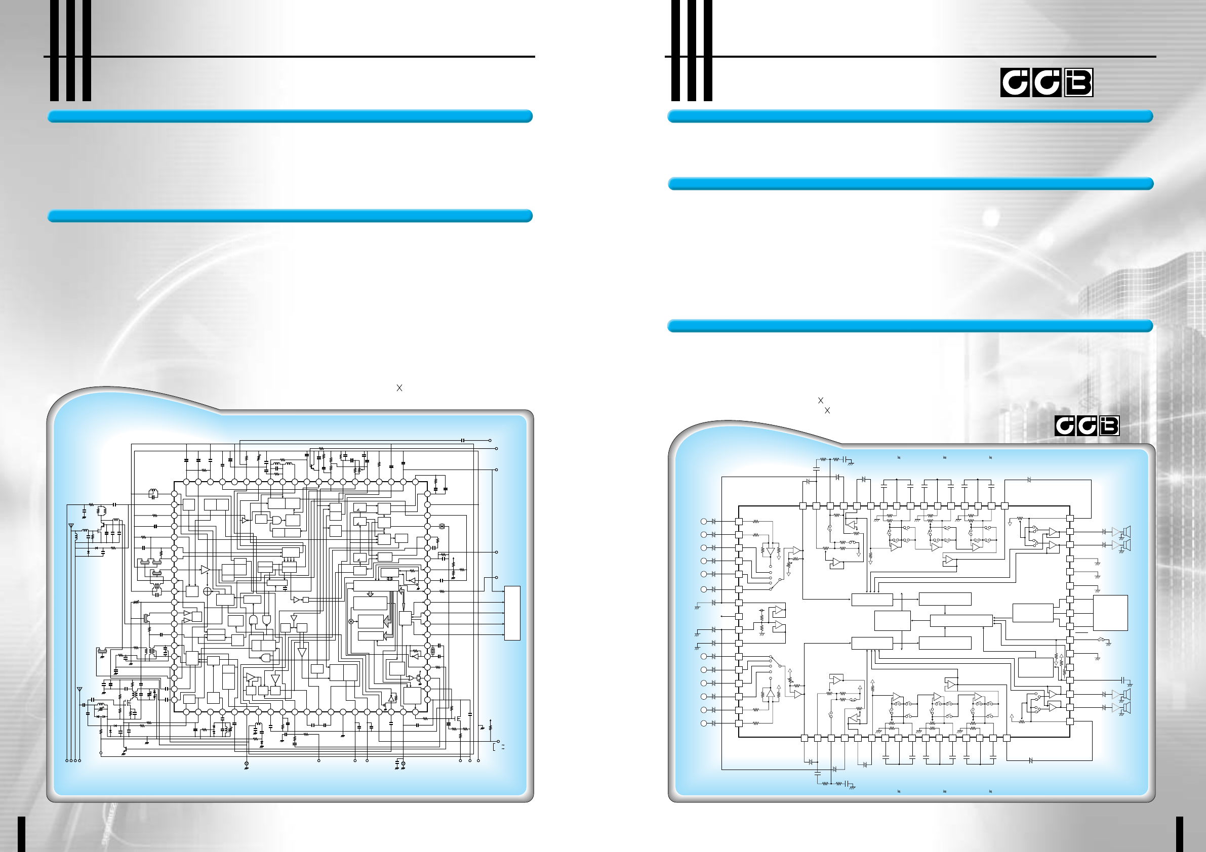
43 Car Audio 44 Car Audio
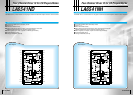
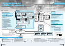
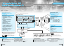
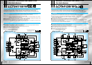
The LA17000M is a car audio system tuner IC that integrates both a PLL frequency synthesizer and all AM/FM
functions on a single chip. The LA17000M combines the functions of two ICs, a PLL IC (such as the LC72144)
and an FM tuner IC (such as the LA1781M) on a single chip that provides PLL, AM (upconversion), FM FE, FM IF,
NC, MCP, and MRC functions. The LA17000M achieves increased performance, adjustment-free manufacturing,
and high reliability at low cost in car tuner systems by providing an optimal functional allocation in the IC.
Car Audio Tuner IC with Built-in PLL CircuitCar Audio Tuner IC with Built-in PLL Circuit
■ Built-in PLL
◆
A/D converter (6 bits, 1 channel)
◆
IF counter and I/O ports for simplified interface
design
◆
Supports AM double conversion reception
■ Strengthened noise reduction
◆
Superlative three-signal characteristics
◆
Improved weak and medium-field NC
characteristics
◆
Improved separation characteristics
◆
Built-in anti-birdie filter (analog and digital outputs)
◆
Anti-multipath sensor outputs
(analog and digital outputs)
■ Support for lower costs
◆
AM double conversion (upconversion)
◆
Improved FM IF circuit (automatic wide/narrow
ceramic filter switching under adjacent channel
interference conditions)
◆
IF gain sample-to-sample variations reduced to 1/3
that in previous devices. This simplifies end product
adjustment during manufacture. Furthermore,
a shifter pin is provided for VSM adjustment.
■ Supports end product miniaturization
◆
High-frequency signal lines can be handled within
the tuner pack.
◆
Easily meets FCC requirements
■ Package: QFP80 (14 14 mm)
Micro controller
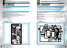
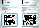
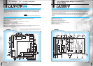
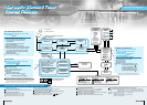
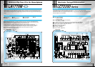
Block Diagram
Block Diagram
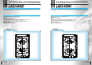
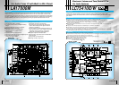
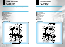
The LC75410E/W is an electronic volume and tone control IC that implements a rich set of audio control
functions with a minimal number of external components. Functions include volume, balance, fader,
bass/midrange/treble, and loudness controls, as well as input selection/switching functions and an input
gain control.
Electronic Volume and Tone Control IC for
Car Audio Systems
Electronic Volume and Tone Control IC for
Car Audio Systems
Overview Overview
Functions
Functions
Features
:CCB is SANYO's original bus format.
All bus addresses are managed by
SANYO for this format.
■ On-chip buffer amplifiers reduce the number of external components
■ Internal switches are implemented in a silicon gate CMOS process that minimizes the noise generated when switching.
This results in low noise even when switching in the no-signal state.
■ Zero-cross switching circuits used for low noise even when input signals are present
■ Built-in VDD/2 reference voltage generation circuit
■ All functions are controlled using serial data (CCB)
■ Packages: LC75410E: QIP64E (14 14 mm)
LC75410W: SQFP64 (10 10 mm)
■ Volume control: A total of 161 positions from 0 dB to -79.5 dB in 0.5 dB steps and -∞ dB.
A balance function can be implemented by controlling the left and right channel volume controls separately.
■ Fader control: The rear or front outputs can be attenuated by one of 16 levels
(A total of 16 settings with attenuations of 0 to -2 dB in 1dB steps, -2 to -20 dB in 2 dB steps, -20 to -30 dB in 10 dB steps,
and -45, -60, and -∞ dB settings.)
■ Bass/midrange/treble controls: Each band can be controlled in 1 dB steps from 0 dB to ±6 dB, and in 2 dB steps from
±8 dB to ±12 dB
■ Input gain control: The input signal can be amplified by 0 to +18.75 dB in 1.25 dB steps
■ Input switching: One of five input systems (left and right channels) can be selected
(Four of the input systems are single-ended inputs, one uses differential inputs.)
■ Loudness control: The -32 dB position of the 2 dB step volume control ladder resistor can be tapped and a loudness
function implemented with external capacitor and resistor components
❋