


LC75412E/WLC75412E/WLC75411E/WLC75411E/W
L4
L3
L2
L1
Vref
V
DD
R1
R2
R3
R4
1µF
1µF
1µF
1µF
PA
10µF
1µF
LVref
22µF
LSELO
LVRIN
LCT
LCOM
LTIN
LF1C1
LF1C2
LF1C3
LF3C1
RF3C1
LVROUT
220pF
68kΩ
4.7kΩ 0.1µF
10µF
10µF
0.1µF0.1µF
10µF
LTOUT
[BASS fo 100Hz] [TREBLE]
LFIN
LFOUT
PA
10µF
LROUT
PA
0.033µF
RROUT
TIM
TEST
PA
10µF
10µF
10µF
10µF
10µF
RFOUT
RFIN
RTOUT
0.1µF
1µF
RVref
RF1C3
RF1C2
RF1C1
RTIN
RVROUT
RCOM
RCT
RVRIN
RSELO
VSS
CL
DI
CE
V
DD
CL
DI
CE
RVref
NO SIGNAL
TIMER
ZERO-CROSS DET
ZERO-CROSS DET
CONTROL
CIRCUIT
4.7kΩ68kΩ
220pF
LVref
LVref
RVref
RVref
LVref
0.1µF
2700pF
0.1µF
2700pF
Micro
Controller
CCB
INTERFACE
LOGIC CIRCUIT
Multiplexer
Multiplexer
+
+
+
+
+
-
+
-
+
-
+
-
+
-
+
-
+
-
+
-
+
+
+
+
+
-
+
-
+
+
+
+
+
+
+
+
+
-
+
+
+
+
+
[BASS fo 100Hz] [TREBLE]
+
-
+
-
+
-
+
-
+
-
+
-
+
-
49
48 47 46 45 44 43 42 41 40 39 38 37 36 35 34 33
32
31
+
L5P
50
L5M
51
L4
52
L3
L2
54
L1
55
56
57
Vref
VDD
58
59
R1
R2
61
R3
62
R4
63
R5M
64
R5P
1µF
1µF
1µF
1µF
1µF
1µF
L6
1µF
1µF
R6
1µF
1µF
1µF
1µF
1µF
1µF
+
PA
10µF
1µF
0.33µF
LVref
LVref
22µF
LSELO
LVRIN
LCT
LF1C1
LF1C2
LF1C3
NC
NC
NC
NC
NC
NC
1000pF
10kΩ
1kΩ
+
10µF
0.1µF
0.1µF
0.001µF
0.001µF
LF3C3
LTOUT
LF3C1
LF3C2
[BASS fo 100Hz] [TREBLE fo 10kHz]
LFIN
LFOUT
30
29
28
+
PA
10µF
LROUT
LAVSS
TEST
PA
0.033µF
RROUT
TIM
NC
18
19
21
20
17
PA
10µF
10µF
10µF
RFOUT
RFIN
16151413
RTOUT
RF3C3
RF3C2
RF3C1
121110
0.33µF
1µF
RVref
RVref
RVref
987
RF1C3
RF1C2
RF1C1
654
NC
NC
NC
NC
NC
NC
3
RCT
2
RVRIN
1
RSELO
27
DVSS
26
CL
25
DI
24
CE
47kΩ
1MΩ
23
MUTE
22
RAVSS
CL
DI
CE
RVref
NO SIGNAL
TIMER
ZERO-CROSS DET
ZERO-CROSS DET
CONTROL
CIRCUIT
1kΩ10kΩ
1000pF
60
LVref
LVref
53
0.1µF
0.1µF
0.001µF
0.001µF
Micro
Controller
LVref
RVref
+
+
+
+
+
+
+
+
+
+
+
+
+
+
+
+
+
-
+
+
-
+
-
+
+
+
-
+
+
-
+
-
+
-
+
-
-
+
-
CCB
INTERFACE
Multiplexer
Multiplexer
LOGIC CIRCUIT
[BASS fo 100Hz] [TREBLE fo 10kHz]
+
-
+
-
+
-
+
-
+
-
+
-
45 Car Audio 46 Car Audio
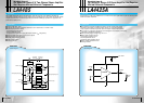
■ Volume control: A total of 81 positions from 0 dB to -79 dB in 1 dB steps and -∞ dB.
A balance function can be implemented by controlling the left and right channel volume controls separately.
■ Fader control: The rear or front outputs can be attenuated by one of 16 levels
(A total of 16 settings with attenuations of 0 to -2 dB in 1 dB steps, -2 to -20 dB in 2 dB steps, -20 to -30 dB in 10 dB steps,
and -45, -60, and -∞ dB settings.)
■ Bass/treble controls: Each band can be controlled in 2 dB steps from 0 dB to ±18 dB
■ Input gain control: The input signal can be amplified by 0 to +18.75 dB in 1.25 dB steps
■ Input switching: One of six input systems (left and right channels) can be selected (Five of the input systems are single-
ended inputs, one uses differential inputs.)
■ Loudness control: Taps are output starting at the -32 dB position of the ladder resistor and a loudness function
implemented with external capacitor and resistor components
Overview
Functions
Features
Overview
Functions
Features
Electronic Volume and Tone Control IC for
Car Audio Systems
Electronic Volume and Tone Control IC for
Car Audio Systems
Electronic Volume and Tone Control IC for
Car Audio Systems
Electronic Volume and Tone Control IC for
Car Audio Systems
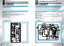
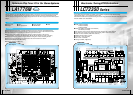
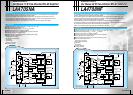
The LC75411E/W is an electronic volume and tone control IC that implements a rich set of audio control
functions with a minimal number of external components. Functions include volume, balance, fader,
bass/treble, and loudness controls, as well as input selection/switching functions and an input gain control.
■ On-chip buffer amplifiers reduce the number of external components
■ Internal switches are implemented in a silicon gate CMOS process that minimizes the noise generated when switching.
This results in low noise even when switching in the no-signal state
■ Zero-cross switching circuits used for low noise even when input signals are present
■ Built-in VDD/2 reference voltage generation circuit
■ All functions are controlled using serial data (CCB)
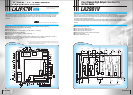
■ Packages: LC75411E: QIP44M (10 10 mm)
LC75411W: SQFP48 (7 7 mm)
■ Volume control: A total of 161 positions from 0 dB to -79.5 dB in 0.5 dB steps and -∞ dB. A balance function can be
implemented by controlling the left and right channel volume controls separately.
■ Fader control: The rear or front outputs can be attenuated by one of 16 levels
(A total of 16 settings with attenuations of 0 to -2 dB in 1 dB steps, -2 to -20 dB in 2 dB steps, -20 to -30 dB in
10 dB steps, and -45, -60, and -∞ dB settings.)
■ Bass/treble controls: Each band can be controlled in 1 dB steps from 0 dB to ±6 dB, and in 2 dB steps from ±8 dB to ±12 dB
■ Input gain control: The input signal can be amplified by 0 to +18.75 dB in 1.25 dB steps
■ Input switching: One of 4 input systems (left and right channels) can be selected
■ Loudness control: The -32 dB position of the 2 dB step volume control ladder resistor can be tapped and a loudness function
implemented with external capacitor and resistor components
:CCB is SANYO's original bus format.
All bus addresses are managed by
SANYO for this format.
❋
:CCB is SANYO's original bus format.
All bus addresses are managed by
SANYO for this format.
❋
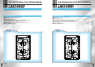
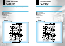
The LC75412E/W is an electronic volume and tone control IC that implements a rich set of audio control
functions with a minimal number of external components. Functions include volume, balance, fader,
bass/treble, and loudness controls, as well as input selection/switching functions and an input gain control.
■ On-chip buffer amplifiers reduce the number of external components
■ Internal switches are implemented in a silicon gate CMOS process that minimizes the noise generated when switching.
This results in low noise even when switching in the no-signal state
■ Zero-cross switching circuits used for low noise even when input signals are present
■ Built-in VDD/2 reference voltage generation circuit
■ All functions are controlled using serial data (CCB)
■ Packages: LC75412E: QIP64E (14 14 mm)
LC75412W: SQFP64 (10 10 mm)
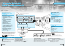
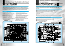
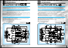
Block DiagramBlock Diagram