


43
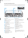
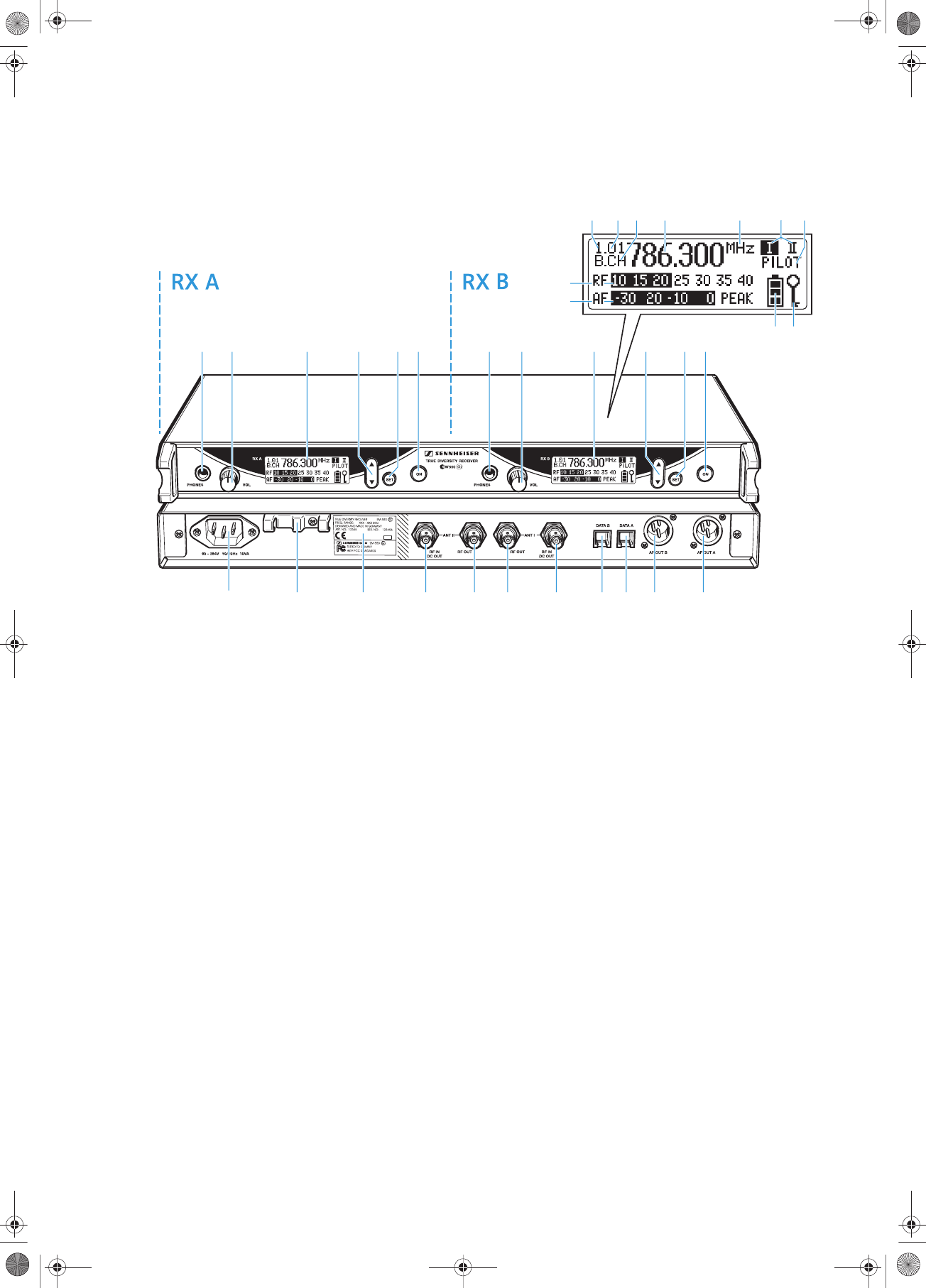
Overview of operating controls
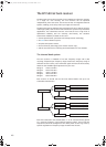
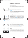
The EM 550 G2 consists of two complete receivers (RX A and RX B) in a 19” rack housing. The two receivers can be
operated independently from each other, therefore all operating controls are available separately for each receiver.
Operating controls Graphic display panel
³ Headphone output (PHONES), ¼” (6.3 mm) jack
socket
· Headphone volume control (VOL)
» Graphic display, backlit
¿ ̆/̄ rocker button, backlit
´ SET button, backlit
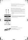
¶ 3-pin IEC mains connector
º Cable grip for mains cable
¾ Type plate
µ BNC socket, antenna input II
(ANT II – RF IN, DC OUT)
¸ BNC socket, cascading output II (ANT II – RF OUT)
¹ BNC socket, cascading output I (ANT I – RF OUT)
Ƹ BNC socket, antenna input I
(ANT I – RF IN, DC OUT)
ƹ Service interface B (DATA B)
ƺ Service interface A (DATA A)
ƻ XLR-3M socket (male) for AF output B,
balanced (AF OUT B)
Ƽ XLR-3M socket (male) for AF output A,
balanced (AF OUT A)
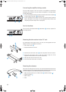
ቢ Display for the current channel bank “1...8, U”
ባ Display for the current channel number “1...20”
ቤ “B.CH“ – abbreviation for channel bank and
channel number
ብ Alphanumeric display
ቦ “MHz“ – appears when the frequency is displayed
ቧ Diversity display
(antenna I or antenna II active)
ቨ “PILOT” display
(pilot tone evaluation is activated)
ቩ Level display for received RF signal “RF”
ቪ Level display for received audio signal “AF”,
with “PEAK“ warning
ቫ 4-step transmitter battery status display
ቭ Lock mode icon
(lock mode is activated)
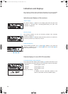
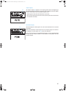
Note:
For further illustrations and examples of the
different standard displays, please refer to the
section “Selecting the standard display” on
page 60.
»³ ·¿´ ² »³ ·¿´ ²
¶ º ¾ µ ¸ ¹ Ƹ ƹ ƺ ƻ Ƽ
ቢ
ቫ ቭ
ቦባ ቤ ብቨቧ
ቩ
ቪ
EM_550_G2.book Seite 43 Donnerstag, 27. November 2003 1:33 13
² ON button, backlit (serves as the ESC (cancel) key
in the operating menu)