


DV-SL2200W
11
DV-SL1200W
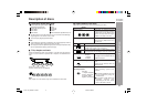
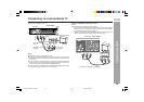
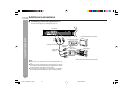
Using RF Modulator
If your TV does not have a Video input socket and has an aerial terminal only,
please purchase the *RF Modulator (not supplied).
(*Please consult your audio/video dealer.)
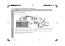
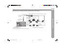
Example: DVD player, TV and RF Modulator connections
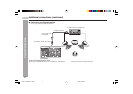
System Connections
Connecting to a conventional TV (continued)Connecting to a conventional)
1. Connect the aerial cable (not supplied) to the ANT. IN terminal of the RF
Modulator.
2. Connect the 75-ohm coaxial cable (not supplied) between the TO TV
terminal of the RF Modulator and the VHF/UHF AERIAL IN terminal of the
TV.
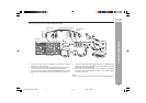
3. Connect the Audio/Video cable (supplied) between the AUDIO OUT and
VIDEO OUT sockets of the DVD player and the AUDIO INPUT and VIDEO
INPUT sockets of the RF Modulator.
4. Turn on the TV, and set the channel number (CHANNEL 3 or CHANNEL 4)
on both TV and RF Modulator, whichever is not used for regular broadcast
in your area.
Note:
For more details, please refer to the instruction manual of the RF Modulator.
A/V INPUT
VHF/UHF
AERIAL
IN
ANT. IN
2
1
3
TO TV
R-AUDIO-LVIDEO
CHANNEL
34
4
DVD player
TV
To VIDEO OUT
socket (Yellow)
(Red) R
(White) L
To AUDIO
OUT sockets
Audio/Video cable (supplied)
RF Modulator
(White) L
(Red) R
To video input
socket (Yellow)
To audio input
sockets
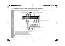
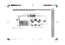
System Connections
(DV-SL1200W)
DV-SL1200_2200W 01-28_EN 6/20/08, 4:48 PM11