


SiI 141B SiI-DS-0037-C
Silicon Image, Inc. 3 Subject to Change without Notice
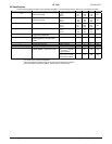
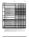
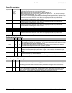
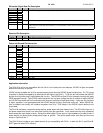
DC Specifications
Under normal operating conditions unless otherwise specified. Low drive strength values, when ST=0, are shown in brackets.
Symbol Parameter Conditions Min Typ Max Units
I
OHD
Output High Drive
Data and Controls
V
OUT
= 2.4
ST=1
ST=0
5.0
2.5
10.3
5.2
17.6
8.8
mA
I
OLD
Output Low Drive
Data and Controls
V
OUT
= 0.4
ST=1
ST=0
-5.5
-2.8
-8.3
-4.2
-11.2
-5.6
mA
I
OHC
ODCK High Drive V
OUT
= 2.4
ST=1
ST=0
10.1
5.0
20.6
10.3
35.1
17.6
mA
I
OLC
ODCK Low Drive V
OUT
= 2.0
ST=1
ST=0
-11.1
-5.5
-16.7
-8.3
-22.4
-11.2
mA
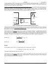
V
ID
Differential Input Voltage
Single Ended Amplitude
75 1000 mV
I
PDL
Output leakage current to ground in
high impedance mode (PD, PDO =
LOW)
10
µA
I
PD
Power-down Current
1
50 100
µA
I
CLKI
Power-down Current RXC± Inactive 4 7 mA
I
PDO
Power-down-output Current 125 155 mA
I
CCR
Receiver Supply Current
ODCK=86MHz, 1-pixel/clock mode
2
C
LOAD
= 10pF
R
EXT_SWING
= 510 Ω
Typical Pattern
3
157
182
mA
C
LOAD
= 10pF
R
EXT_SWING
= 510 Ω
Worst Case Pattern
4
172
194
mA
Notes:
1
The transmitter must be in power-down mode, powered off, or disconnected for the current to be under this maximum.
2
For worst case I/O power consumption.
3
The Typical Pattern contains a gray scale area, checkerboard area, and text.
4
Black and white checkerboard pattern, each checker is one pixel wide.