


– 41 –
NOTE:
• -XX and -X mean standardized parts, so they
may have some difference from the original
one.
• Color Indication of Appearrance Parts
Example:
KNOB, BALANCE (WHITE) . . . (RED)
↑↑
Parts Color Cabinet's Color
• Items marked “*” are not stocked since they
are seldom required for routine service. Some
delay should be anticipated when ordering
these items.
• The mechanical parts with no reference num-
ber in the exploded views are not supplied.
• Hardware (# mark) list and accessories and
packing materials are given in the last of the
electrical parts list.
The components identified by mark
! or dotted line with mark ! are
critical for safety.
Replace only with part number
specified.
Les composants identifiés par une
marque ! sont critiquens pour la
sécurité.
Ne les remplacer que par une pièce
portant le neméro spécifié.
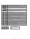
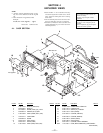
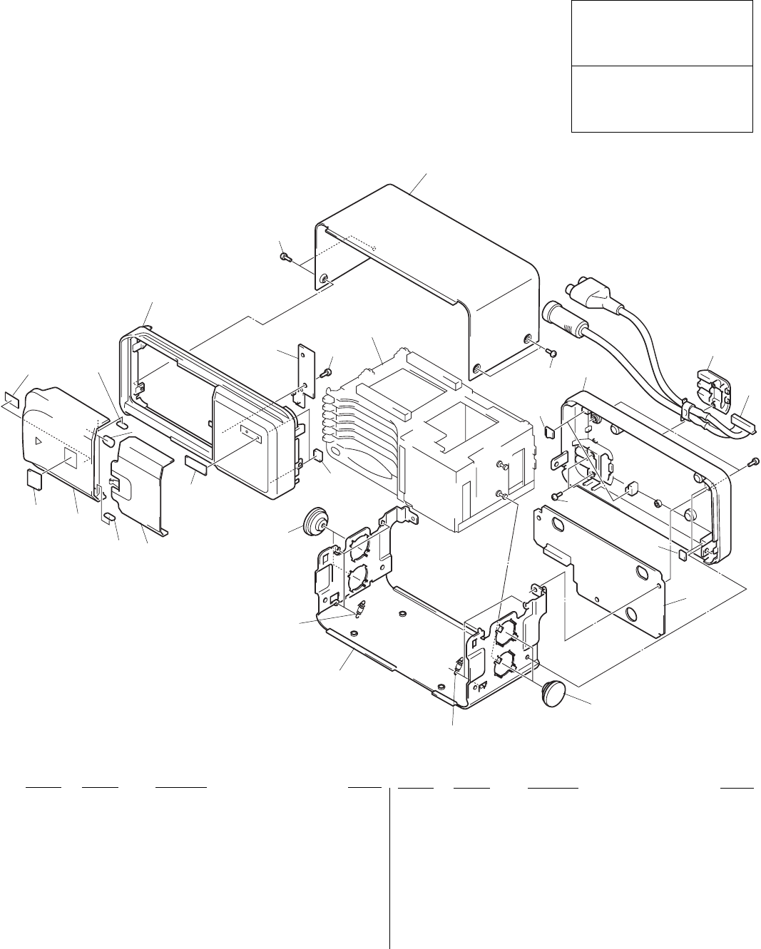
4-1. CASE SECTION
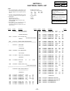
SECTION 4
EXPLODED VIEWS
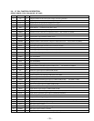
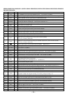
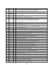
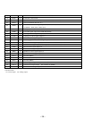
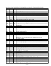
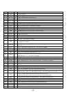
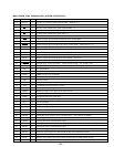
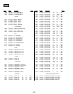
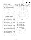
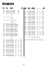
Ref. No. Part No. Description Remark
Ref. No. Part No. Description Remark
* 11 A-3294-228-A POWER BOARD, COMPLETE
12 3-930-176-01 DAMPER (798)
13 3-930-177-01 SPRING (FL), TENSION
* 14 3-930-173-31 CASE (LOWER)
15 3-931-697-01 CUSHION (STOPPER)
16 3-348-750-01 CUSHION (DAMPER)
17 3-930-744-01 SPACER (DOOR)
18 3-933-740-01 SHEET (SLIDE)
19 3-831-441-11 CUSHION, RATTLE ABSORBER
CNP1 1-776-105-11 CORD (WITH CONNECTOR) (BUS CONTROL/
RCA PIN JACK)
1 X-3371-273-1 DOOR (S) ASSY(/EXP)
2 3-930-168-11 DOOR (P)
3 3-912-956-11 SCREW (2.6X6) (CU), +BVTT
4 4-969-961-01 EMBLEM (NO.4), SONY
5 X-3373-364-1 PANEL (FRONT) ASSY (/EXP)
* 6 1-664-517-11 LAMP BOARD
7 3-909-607-01 SCREW
* 8 3-930-172-31 CASE (UPPER)
9 3-930-175-11 COVER (CORD)
10 X-3371-225-1 PANEL (REAR) ASSY (/EXP)
11
#1
CNP1
7
15
12
13
14
13
15
3
7
6
MG-798-133
17
18
1
17
2
not supplied
19
4
12
9
10
16
3
8
5