


5
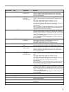
Locations and Functions of Parts and Controls
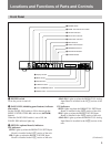
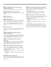
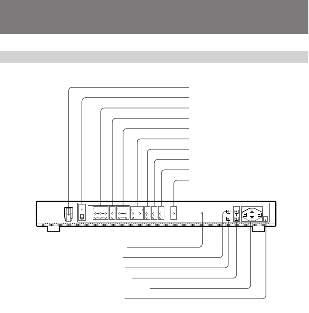
Front Panel
(Continued)
1
¬
POWER
PANEL
INH
SDTI
IN1
IN2
IN1
IN2
EXT 525
625
36M
18M
7/8
3/4
ANALOG
SDI CH3/4CH1/2
OPTION
REF ALARM
MENU ITEM
RESET
ENTER
INPUT
SEL
FEC
RATE
FREQ
BW
AUDIO
SEL
VIDEO
STD
1 POWER switch
2 PANEL INH indicator and switch
3 OPTION indicators
4 INPUT SEL indicators
5 AUDIO SEL indicators
6 REF indicators
8 FREQ BW indicators
7 VIDEO STD indicators
9 FEC RATE indicators
!º ALARM indicator
!¡ Display window
!™ MENU button
!£ ENTER button
!¢ ITEM Â/µ buttons
!∞ Cursor (4/$/“/”) buttons
!§ RESET button
1 POWER switch
Turns the power on and off.
2 PANEL INH (inhibiting panel buttons) indicator
and switch
Set the PANEL INH switch to ON to deactivate the
MENU, ENTER, ITEM Â/µ, and cursor (4/$/“/”)
buttons.
When the PANEL INH switch is set to ON, the
PANEL INH indicator lights up.
3 OPTION (optional boards) indicators
IN1 indicators
SDTI: Lights up when the BKSM-T101 SDTI Input
Board is installed in the IN1 section of the unit.
SDI: Lights up when the BKSM-T102 SDI Input
Board is installed in the IN1 section of the unit.
ANALOG: Lights up when the BKSM-T103 Analog
Input Board is installed in the IN1 section of the
unit.
IN2 indicators
SDTI: Lights up when the BKSM-T101 SDTI Input
Board is installed in the IN2 section of the unit.
SDI: Lights up when the BKSM-T102 SDI Input
Board is installed in the IN2 section of the unit.
ANALOG: Lights up when the BKSM-T103 Analog
Input Board is installed in the IN2 section of the
unit.