


CM
I
N
T
E
R
T
E
K
L
I
S
T
E
D
C
US
THIS CLASS D DIGITAL DEVICE MEETS ALL REQUIREMENTS OF THE
CANADIAN INTERFERENCE-CAUSING EQUIPMENT REGULATIONS AND
COMPLIES WITH PART 15 OF THE FCC RULES.
OPERATION SUBJECT TO CONDITIONS STATED IN THE MANUAL.
WARNING
TO REDUCE THE RISK OF FIRE OR ELECTRIC
SHOCK DO NOT EXPOSE THIS EQUIPMENT TO
RAIN OR MOISTURE
AVIS:
RISQUE DE CHOC ELECTRIQUE-NE PAS
OUVRIR.
CAUTION
MANUFACTURED IN THE UNITED KINGDOM
- LIMIT
- SIGNAL
- POWER
FUSE
T10AL 250V
USER DSP
ON - OFF
INPUT
LINK
NETWORK
IN
NETWORK
LINK
THIS EQUIPMENT MUST BE EARTHED
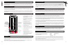
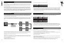
A ‘LIMIT/NETWORK
FOUND’LED displays
DSP limiter action for both
output channels. Also
duplicates the function of
the front mounted network
found LED
A ‘LIMIT/NETWORK
FOUND’LED displays
DSP limiter action for both
output channels. Also
duplicates the function of
the front mounted network
found LED
A green signal present LED,
operating at -50dB relative
to the minimum input level
XLR female audio input
XLR male audio link
RJ45 network input RJ45 network link
Rocker power switch
Rugged Neutrik Powercon
locking mains connector
Fuse Holder
A user DSP ON/OFF
switch
In the OFF position this will
return the loudspeaker to
the factory default settings
A ‘NETWORK FOUND’ LED,
mounted on the front of the
cabinet, software controlled
to enable location of specific
nodes on the network
Amplifier & DSP Panel
Power LED
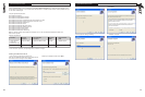
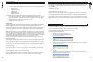
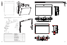
3.0: UNPACKING AND VISUAL CHECKS
Every Tannoy VNET™ product is carefully tested and inspected before being packaged and leaving the factory. After unpacking
your loudspeaker, please inspect for any exterior physical damage, and save the carton and any relevant packaging materials
in case the loudspeaker again requires packing and shipping. In the event that damage has been sustained in transit notify
your dealer immediately.
3.1: PRELIMINARY RECOMMENDATION
A word of warning on high sound levels - these speakers are capable of generating high output levels over sustained periods
of time and such levels, over 95dBspl for 8 hours per day, can eventually cause permanent hearing loss. Since Tannoy
loudspeakers have a natural-sounding flat frequency response and low distortion, it's possible not to be aware just how high
the sound level is high while working with them.
For continuous exposure we recommend the occasional use of a sound level meter. This should be capable of integrating the
sound level over a period of exposure according to noise control standards and used just to check that noise levels are always
within safety limits.
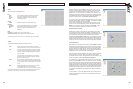
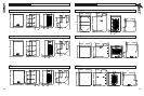
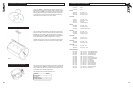
4.0: INTERFACE PANEL
6 7
TM
• XLR FEMALE AUDIO INPUT – This is a lockable
XLR line input socket for connection to the audio
source. Fully Balanced.
Pin 2 Hot (+), Pin 3 Cold (+), & Pin 1 Ground.
• XLR MALE AUDIO LINK - This is a lockable XLR
line output socket to link additional speakers.
Fully Balanced.
Pin 2 Hot (+), Pin 3 Cold (+), & Pin 1 Ground.
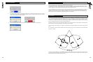
• RJ45 NETWORK INPUT - For Control and
monitoring functions over RS485.
• RJ45 NETWORK LINK - For linking cabinets.
Vnet supports free network topology.
Cabinets can be ‘daisy chained’ or linked in a
‘star’ configuration, or a combination of both.
• ROCKER POWER SWITCH – Turns AC power
on to the unit (100V – 240V)
• FUSE HOLDER – Replace only with 10A 230V
anti-surge fuse. Tannoy part Number 3461 0919.
• AC MAINS CONNECOR – Neutrik Powercon
mains connector (supplied)
• USER DSP ON/OFF SWITCH
• POWER LED – Blue LED indicates when power
has been applied to the speaker.
• LIMIT/NETWORK FOUND LED – Also mounted
on the front of the cabinet. This can be seen
clearly from behind the grill when activated.
• SIGNAL PRESENT LED
5.1: AC POWER REQUIREMENTS
AC Power Requirements
VNET™ products are equipped with Neutrik Powercon™ mains connectors which mate with the Neutrik NAC3FCA Cable
connector, quick lock with a securing lever for power-in. This AC mains connector is supplied with each VNET™ product. The
amplifier operates between the ranges of 100 to 240 Volts; the auto ranging power supply detects the mains voltage automatically
and configures accordingly. Replace the mains fuse only with the same T10A HBC type supplied by Tannoy under part number
3461 0919.
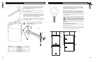
5.2 COOLING
Do not install this equipment in an enclosed space. Do not limit free ventilation and movement of air around the back panel.
Ensure that there is at least 100mm (4") of space around all sides of the product for ventilation. An efficient switch mode power
supply has less weight, less current draw and more efficient mechanical cooling; meaning that no fans are required. In an area
with a relatively high ambient temperature the heatsink can reach temperatures of up to 65 degrees C, this is perfectly normal.
5.3 LED FUNCTIONS
On switch on all of the LED’s will illuminate instantaneously. The first to go off is the green signal LED after about 1 second.
The red limit LED will flash for 5-10 seconds, this is the unit performing a self diagnostic test. During this initial few seconds
the audio is muted until the red LED stops flashing & the blue power LED is the only LED left illuminated.
After the self diagnostic test is performed, the unit is ready to pass audio. When audio is detected the green signal LED will
illuminate. If at any time the Red LED flashes this indicates that the DSP is taking corrective action by applying limiting to either
the LF or HF channels (or both). Regular flickering of the Limit LED is perfectly acceptable; do not allow the limit LED to stay
on constantly for any sustained length of time (reduce the gain).
Fast regular flashing of the red LED indicates that the DSP is taking protective action; the input will be automatically attenuated
to avoid over driving, if this occurs the operator should reduce the input gain from the source. If the gain is not reduced the
unit will eventually be shut down by the DSP.
The blue ‘Network Find’ LED on the front of the cabinet (behind the grill) can only be illuminated by activation from within the
software interface. When activated the LED will flash intensely as an aid to locate and identify loudspeakers connected on
the network. The red limit LED on the back panel also doubles as a ‘network find’ LED duplicating the function of the blue front
mounted LED.
5.4 LIMITERS
The limiters are carefully set-up to preserve the loudspeakers dynamic headroom by allowing short term transients to pass;
audible degradation in sound will only become apparent when the limit indication is on constantly. The limiting functions will
protect the amplifier from long term overheating by attenuating the driving voltage to the drive units. If used irresponsibly
(constant hard clipping) sound quality will be compromised. In extreme cases drive units may also be damaged.
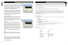
5.5: AUDIO CONNECTIONS
Audio Connections
The signal input & link connectors are fully balanced. SIGNAL XLR CONNECTOR
When connecting a balanced signal be sure to wire Hot (+) Pin 2
to the following standard:- Cold (-) Pin 3
Shield (GND) Pin 1
In a standard balanced interconnection there are two signal conductors and a shield. The shield is normally referenced to
ground at one or both ends. Many times the shield is lifted at one end, usually at the input to eliminate "ground loops" or
noise. The problem with this approach is that while it may reduce hum, the shields act as radio antennas and pickup radio
frequency interference from the environment.
Multiple enclosures may be driven from a single audio source; simply plug the signal source output into the first XLR input
socket, and patch that speakers XLR link to the next speakers XLR input socket & so on.
5.0: OPERATION
The range of products are fully integrated designs, all speaker management functions which include driver EQ, dynamic
limiting, & crossover functions are carried out within the DSP, therefore the need for external amplification, active crossovers
and limiters is not required. The only input from the user is crossover between full range cabinets & subwoofers, and room
equalization (if necessary).
When routing audio, units may be daisy chained together by linking the Input/link XLR connectors. It is necessary to have
power local to each speaker, as it is not possible to daisy chain the AC power connectors.