


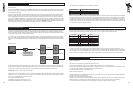
6.0: NETWORK CONNECTIONS
Interconnection between the network computer and the speakers is very straight forward, using twisted pair cable and simple
connectors. The RS485 interface operates on a shared bus so that a single computer can control any amplifier on the bus,
and the computer may gather status information from any device on the bus. Each module contains a unique address so that
no user input will be required to configure network nodes.
It is only data that is carried over the network to control setup functions & ongoing system diagnostics, therefore if a network
fault occurs, audio can still be delivered. This alleviates the problem of total system failure through a single system controller
going down. As each loudspeaker controls it own DSP functions any unforeseen failure would be isolated to only that particular
‘node’.
RS-485 is standard for sending serial data. It uses a pair of wires to send a differential signal over distances up to 4000 feet
(1200m) without a repeater. The differential signal makes it very robust, RS-485 is one of the most popular communications
methods used in industrial applications where it’s noise immunity and long-distance capability are a perfect fit.
IMPORTANT: Always run a signal ground with RS-485
Connection from the PC to the network is via a 3
rd
party RS232 to RS485 or USB to RS485 interface. These devices are readily
available from your IT supplier. At the time of writing this manual extensive testing was carried out with the following devices:-
Tannoy USB – RS485 Converter (Part No. 8001 3920)
K2 from KK (www.kksystems.com)
USB-COMi from Easysync (www.easysync.co.uk)
485 SD9R from B&B electronics (www.bb-elec.com)
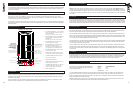
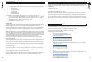
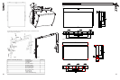
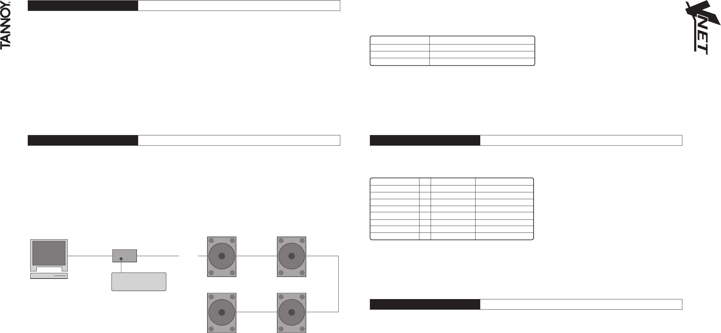
example network
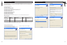
5.6: USER DSP ON/OFF
A user DSP On/Off switch is provided on the amp panel. This miniature switch is recessed and can be easily activated with a
small screwdriver.
The switch in the ‘OFF’ position will return the VNET™ loudspeaker back to the ‘original’ factory settings, this basically means
that any parameter edited in software (EQ, Crossover, Mute, Delay) can be defeated by activating this switch. This can be a
very useful feature. Example:-
In a large corporate production the networked loudspeakers are been used by an operator who has been using the Podware
software for editing EQ & gain & delay; at the end of the performance he mutes the loudspeakers from within the software
and the loudspeakers are returned to ‘hire stock’ after the performance. Next day there is a rush for a small hire comprising
only a couple of VNET™ loudspeakers. The speakers are taken to the small gig where the operator is not making use of the
Networking, or Podware software in this particular instance. He realizes that he muted the loudspeakers the night before, and
this particular pair had 100ms of delay applied!! All he has to do is flick the USER DSP switch to the ‘OFF’ position (assuming
he is carrying his Leatherman) and any of the USER editable parameters in Podware are defeated.
8 9
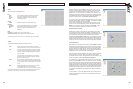
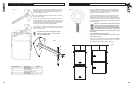
4.5: USER DSP ON/OFF
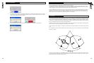
Connections from the RS485 device to the speaker is as follows:-
From RS485 Device RJ45 To Vnet Network
B+ Pin 1
A - Pin 2
GND Pin 5
Network connections between nodes are via rugged Neutrik ‘ethercon’ connectors; these are high quality and are compatible
with standard RJ45 plugs. Node connections are made using standard RJ45 connectors and CAT5 cable. Long runs should
be solid core, but standard is fine. The implication is that stranded is more robust and less prone to breakage, it is therefore
suggested that solid should be used for install applications while stranded is better suited to rental applications. Cabinets can
be ‘daisy chained’ or linked in a ‘star’ configuration, or a combination of both. Quality termination of all connectors at each node
is essential for the network to function correctly.
TM
VNET Series VNET Series
VNET Series VNET Series
RS485 link
RS485 link
RS485
3rd party RS232/
USB to RS485 interface
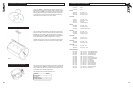
6.1 LINKING CABINETS
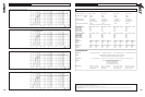
The table below shows the standard ‘straight-through’ convention for CAT5 patch cables (clip down) . These can be used
between network nodes. Bear in mind though that only Pins 1, 2, & 5 are used to link the network together.
P1 (pin No.) V P2 (pin No.) Colour
1 V 1 White/Orange
2 V 2 Orange
3 V 3 White/Green
4 V 4 Blue
5 V 5 White/Blue
6 V 6 Green
7 V 7 White/Brown
8 V 8 Brown
To aid the construction of very large networks each speaker provides a source of power (+12Volts) on the network ‘Link’
connector that can be used to seamlessly power network extenders or repeaters that large networks may require. This power
can be located on pin 4 on the ‘NETWORK LINK’ connector. This power is passed between the ’NETWORK IN’ & ‘NETWORK
LINK’ connectors if the speaker is powered off to ensure that upstream net powered devices continue to receive power.
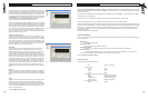
7.0 SOFTWARE INSTALLATION
The enclosed disc contains the Podware software package; a comprehensive editor, interface, & diagnostics tool for the VNET™
range of loudspeakers.
Check the Tannoy website for any updates http://www.tannoy.com
The disk should ‘AUTORUN’, if not open the ‘Podware’ folder & double click on the ‘Setup.exe’ icon.
Your PC will need to have the Windows .NET Framework installed. If it does not, you will be directed to the necessary location
to do so http://msdn.microsoft.com/netframework/downloads/framework1_1/
The .NET Framework is also on your installation CD.
What is the .NET Framework?
The .NET Framework is an integral Windows component for building and running the next generation of software applications
and Web services. The .NET Framework:
Supports over 20 different programming languages.
Manages much of the plumbing involved in developing software, enabling developers to focus on the core business logic code.
Makes it easier than ever before to build, deploy, and administer secure, robust, and high-performing applications.
The .NET Framework is composed of the common language runtime and a unified set of class libraries.
RS485 link