


TASCAM US-16x08
15
6 – Using the Settings Panel
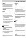
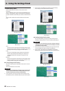
2 COMPRESSOR
When the input volume exceeds the THRESHOLD level,
the input volume is compressed, reducing output volume
variation.
For example, by reducing the high level parts of sounds
as they occur, a more even volume level throughout can
be achieved. This allows lower-level sounds to be raised,
resulting in a fuller sound.
Three meters show the level of the signal input to the
compressor (INPUT), the level of the signal output from the
compressor (OUTPUT) and the gain reduction caused by the
compressor (GR).
THRESHOLD knob
Sets the threshold level that will cause the effect to start.
Range: −32 dB – 0 dB (default: 0 dB)
RATIO knob
Sets the compression ratio for the input volume.
Turning it right raises the compression ratio, increasing
the amount of compression.
Range: 1.0:1 – inf:1 (default: 1.0:1)
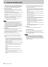
GAIN knob
Sets the gain of the output signal.
When the volume is compressed, the output level
becomes lower than the input level. Use the GAIN knob
to increase the output level so that it is close to the input
level.
Range: 0 dB – 20 dB (default: 0 dB)
ATTACK knob
Sets the amount of time until the compression reaches
the compression RATIO setting after the input volume
exceeds the threshold.
Range: 2 ms – 200 ms (default: 2 ms)
RELEASE knob
Sets the amount of time until the compression stops and
the sound returns to its uncompressed level after the
input sound goes below the threshold.
Range: 10 ms – 1000 ms (default: 10 ms)
To set the compressor for a channel, select its Analog X
button (3).
The compressor settings will be shown for the channel
selected by its Analog X button (3).
NOTE
•
If the input is a stereo signal (stereo-linked channel or
master), compression will start and be applied to both
channels when either the left or right input channel exceeds
the threshold level.
•
When the compressor is off, the compressor curve will
appear but the meters will not be active.
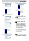
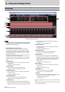
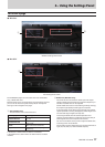
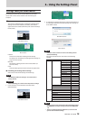
3 Analog X buttons
When an Analog X button ("X” is the channel number) is on
(lit), the equalizer (1) and compressor (2) settings for that
channel will be shown and can be adjusted as desired.
Off (default): Analog X button unlit
On: Analog X button lit
You can only select one channel at a time. Multiple Analog X
buttons cannot be on at the same time.
When a channel is selected, click a different channel's button
to select that channel. The previously selected channel
button will become unlit, and the newly selected channel
button will light.
4 PHASE buttons
Turn a PHASE button on to reverse the phase of that
channel.
5 EQ buttons
Turn an EQ button on to enable the equalizer on that
channel.
6 COMP buttons
Turn a COMP button on to enable the compressor on that
channel.
7 SOLO buttons
Turn a SOLO button on to solo that channel.
With this unit, when the SOLO button of a channel is
enabled, all other channels are automatically muted (solo-in-
place monitoring).
The MUTE buttons for channels that are muted will light.
(Default: off)
Multiple channels can be soloed at the same time.
NOTE
•
When all the SOLO buttons are off, clicking the SOLO
button of one channel will put the unit into solo mode and
automatically mute the other channels, lighting their MUTE
buttons.
•
When all SOLO buttons are disabled, channels that had
been automatically muted will become unmuted. Channels
that had been individually muted before the unit entered
solo mode will remain muted.
•
The MASTER L/R channel MUTE button will not turn on
automatically when the unit enters solo mode.
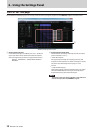
8 MUTE buttons
Turn a MUTE button on to mute that channel.
(Default: off)
NOTE
In addition to turning the MUTE button on and off, channels
will be automatically muted and unmuted when SOLO
buttons are used
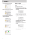
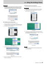
9 Pan sliders
Use these to adjust the stereo positions of the signals input
to each channel when they are sent to the stereo bus.
Use the mouse to click and drag a pan slider left or right to
adjust the position.
While dragging the mouse, the value being adjusted is
shown in its fader level display area (above 0).
The value is L20 when set all the way to the left, C when set
in the center and R20 when set all the way to the right.
Setting range: L20 – L1, C (default), R1 – R20 (41 steps
total with C at the center and 20 steps to both left and
right.)
A pan slider appears blue when centered (C) and yellow at
all other positions.
NOTE
•
If a pan slider is centered (C), the signal is reduced by 3 dB
and sent to both the left and right channels of the stereo
bus.
•
Double-click a pan slider to return it to the center (C)
position.
•
When a pan slider is set to the left end (L20), the signal for
that channel is sent only to the left channel of the stereo
bus. It is not sent to the right channel of the stereo bus.