


Sec tion
4
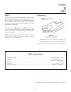
FM-1 Fre quency Man ager
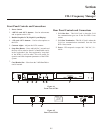
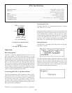
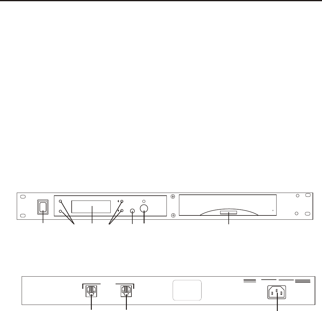
Front Panel Con trols and Con nec tions
1.
Power Switch.
2.
<MENU> and <SET> but tons – Used to se lect menus
and set op tions on the LCD.
3.
Backlit Graphics LCD (Liq uid Crys tal Dis play).
4.
<UP> and <SET> but tons – Used to se lect op tions on
the LCD.
5.
Con trast Ad just – Ad justs the LCD's con trast.
6.
Snap Shot But ton – Press and hold for 2 sec onds and
the user will be asked to check if a DataFlash® card is
in the "card reader" slot. Press again and a "snap shot"
of the BTR-1(s) will be taken. This will re cord fre -
quen cies and other im por tant pa ram e ters of the BTR-1
sys tem.
7.
Card Reader Slot – Slot where the 2 MB DataFlash®
card is in serted.
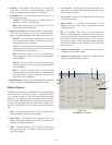
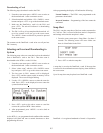
Rear Panel Con trols and Con nec tions
1.
CAN Bus Out – This RJ-45 jack is where the CAN
bus com mu ni ca tion goes out to the first BTR-1 base
sta tion.
2.
CAN Bus Ter mi na tion - This RJ-45 jack is where the
CAN bus com mu ni ca tion ter mi nates from the last
BTR-1 base sta tion.
3.
Power – IEC re cep ta cle. Ac cepts 100 – 240 VAC, 50 –
60 Hz.
Fig ure 4-1
Front View of FM-1
Fig ure 4-2
Rear View of FM-1
4-1
RadioCom
FM-1
Telex
RE
A
D
R
D
E
A
R
C
MENU
SET
UP
DOWN
SNAP SHOT
TM
R
1
2
3
4 5
6
7
POWER
100-240 VAC 50-60 Hz
TERMINATIONOUT
CAN BUS
1 2 3
RadioCom
FM-1
SYSTEMS MANAGER
P/N: 879830
S.N.: 0001
Telex Communications, Inc.Telex Communications, Inc.
8601 East Cornhusker Highway, Lincoln, NE 68507
Made in U.S.A.Made in U.S.A. 803995
TM