


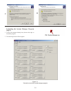

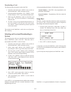


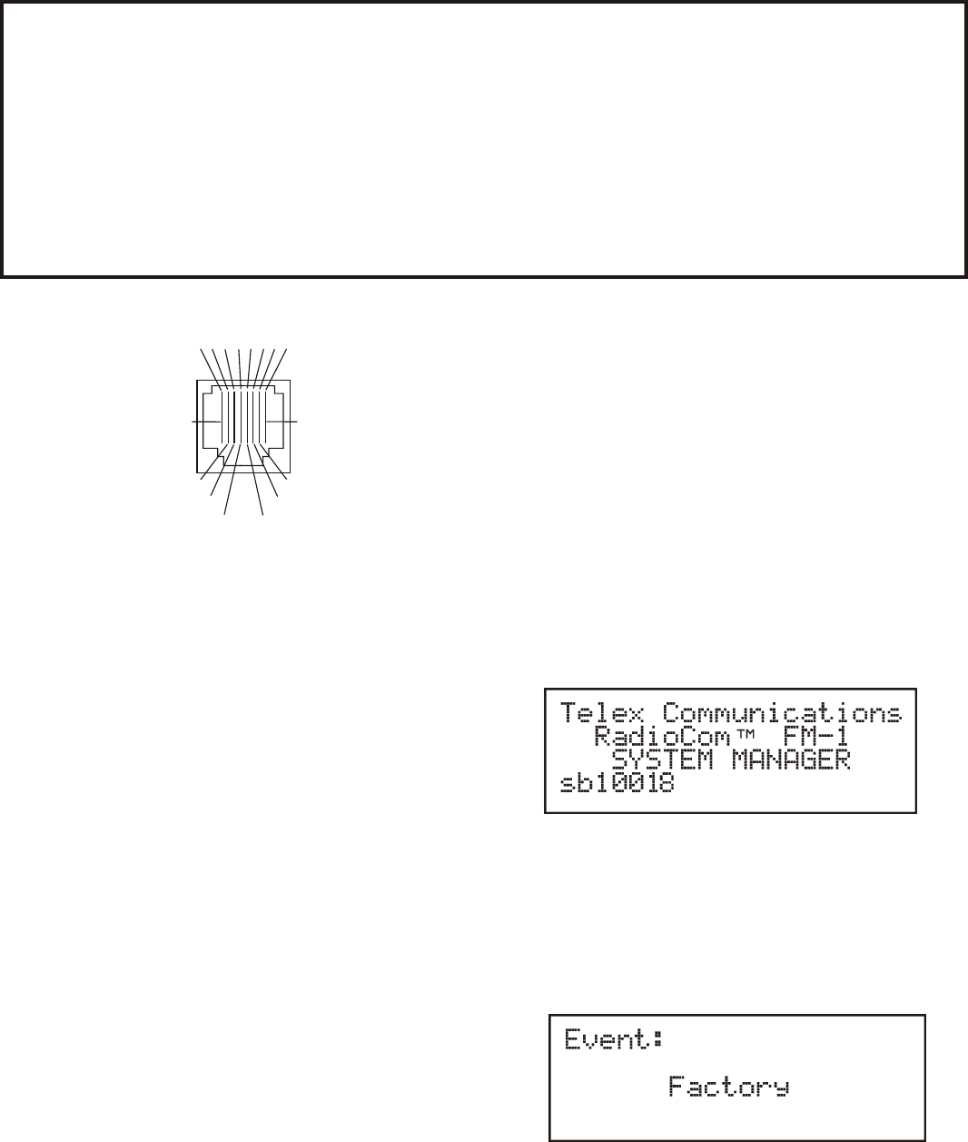
Figure4-3
CAN Bus OUT RJ-45 Pinout
Op er a tion
Ba sic De scrip tion
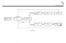
The FM-1 (Fre quency Man ager) in ter faces with up to ten
BTR-1 base sta tions. The FM-1 talks to the bases via a CAN
bus sys tem. The CAN bus starts at the FM-1 and daisy chains
through all the base sta tions and then back to the FM-1 to ter --
mi nate. The flash card is in serted in the card reader slot for the
FM-1 to read events from the card. With the flash card in the
FM-1 the user can se lect an event on the card and download
the se lected event. Now the user can down load the event into
the base sta tions. The FM-1 can also take “snap shots” of the
ten pack of bases and down load those pa ram e ters on the flash
card for even tu ally up loading into the SMP.
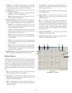
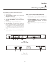
Con nect ing the FM-1 to the Base Sta tions
The FM-1 com mu ni cates to the base sta tions via the CAN bus.
This CAN bus starts at the FM-1 “OUT” port. It is con nected
from there to the first base sta tion. It does not mat ter which
CAN bus base sta tion jack is the in put or out put. From the
first base it daisy chains through all the base sta tions (up to
ten). The CAN bus con nects from the last base sta tion to the
FM-1 port marked “Ter mi na tion”.
DataFlash® is a reg is tered trade mark of Atmel® Cor po ra tion
Pow er ing the Unit
The in put to the FM-1 is a stan dard IEC con nec tor. It ac cepts
100 – 240 VAC, 50 – 60 Hz.
If the unit has been con nected to AC power for some time, and
the front panel switch is turned on, the unit will power-up al --
most in stan ta neously. How ever, if the unit has its’ power
switch in the on po si tion and is then pow ered by VAC volt age
via the rear panel the unit will take 3 to 4 sec onds to
power-up. This is nor mal, the in ter nal power sup ply of the
FM-1 takes 3 to 4 sec ond to power up if pow ered-up cold.
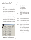
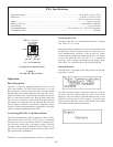
Start-up Screen
When the FM-1 is pow ered-up the start-up srceen will be dis --
played for 5 sec onds.
The lower left-hand cor ner con tains the soft ware ver sion in
the FM-1. Af ter the start-up screen the event screen will be
dis played. The event screen is the main de fault screen. It will
dis play the cur rent event in FM-1 mem ory. Up to 99 events
may be stored in the FM-1 and on a card, see the "FM-1 Menu
Flow Chart sec tion for the menu struc ture.
4-2
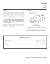
FM-1 Spec i fi ca tions
Tem per a ture Range..................................................................................................................-4°F to 130°F (-20°C to 55°C)
Di men sions...................................................................................................................................19.0”W x 1.72”H x 8.02”D
(48.3 cm x 4.4 cm x 20.4 cm)
Weight.......................................................................................................................................................3 lbs 9 oz (1.62 kg)
Mem ory Card Type...........................................................................................................................DataFlashâ, 2 MB Only
Event Stor age .................................................................................................................................................Up to 99 Events
Power Re quire ments ..........................................................................................100 – 240 VAC, 50 – 60 Hz, IEC re cep ta cle
Com mu ni ca tion Bus.................................................................................................................................................CAN Bus
PIN
21
3
4 5 6 7 8
3.3 VDC
NC
NC
CAN LOW
CAN HIGH
NC
GND
NC
NC = Not Connected
(Look ing at rear panel of FM-1)