© Titan Tool Inc. All rights reserved. 11
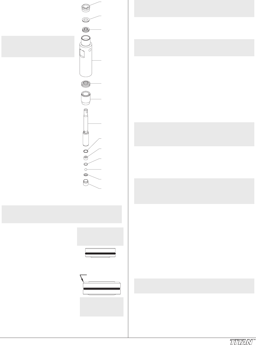
Piston Rod
Cylinder
Seal
Retainer
Upper
Packing
Assembly
Adapter
Outlet Valv
Seal
Outlet Valv
Cage
Nylon
Washer
Outlet Valv
Ball
Outlet Valv
Seat
Outlet Valv
Upper
Support
Ring
Lower
Packing
Assembly
20. Remove the cylinder from the vise.
21. Insert the connection pin through
the hole at the top of the piston
rod and clamp each end of the
connecting pin in the vise. This will
hold the piston rod in position for
disassembly.
NOTE: Do not clamp the piston
rod directly in the vise.
Damage to the piston rod
will occur.
22. Using a 3/8” hex wrench, loosen
and remove the outlet valve
retainer from the piston rod.
23. Remove the outlet valve seat,
outlet valve ball, nylon washer,
outlet valve cage, and outlet valve
seal from the piston rod.
24. Clean out any debris and examine
the retainer and outlet valve seat.
If the seat is damaged, reverse or
replace the seat.
25. Clean and inspect the outlet valve
cage and outlet valve ball. Replace
if they are worn or damaged.
26. Reassemble the outlet valve
assembly into the piston rod in
the reverse order of how it was
disassembled. Torque the outlet
valve retainer to 12 ft. lbs.
27. Remove the piston rod from the
vise.
28. Clean the cylinder. Inspect the
cylinder for damage and replace if
necessary.
29. Place the cylinder upright in a vise
by clamping on the wrench ats.
30. Locate the new upper and lower
packings and remove the pre-form
tools. Save the upper packing
pre-form tool for use as the piston
insertion tool later in this procedure.
NOTE: Do not remove the pre-form tools from the upper
and lower packings until immediately before they
are installed into the cylinder.
Install upper packing
with raised lip
facing down.
Raised Lip
31. Pack the areas between the packing
lips with grease. Lubricate the
o-rings on the exterior of the
packings with grease.
32. Insert the upper packing into the
top of the cylinder with the raised
lip on the packing facing down
toward the cylinder.
33. Insert the upper support ring on top of the upper packing.
Large Beveled Edge
Install lower packing so
large beveled edge will
be facing up when the
cylinder is upright.
34. Thread the upper seal retainer into
the cylinder and torque to 25-30 ft.
lbs.
35. Rotate the cylinder in the vise so that
the bottom end is facing up.
36. Insert the lower packing partially into
the bottom of the cylinder with the
large beveled edge facing toward the
cylinder (beveled edge will be facing
up when the cylinder is upright).
37. Push the lower packing assembly
into position using the lower packing insertion tool (see Fluid
Section Assembly parts list for lower packing insertion tool
P/N).
NOTE: Coat the piston insertion tool (i.e. upper packing
pre-form tool) and the piston rod with grease
before inserting them into the cylinder.
38. Place the piston insertion tool over the top of the piston rod.
39. Insert the piston rod into the bottom of the cylinder, through
the lower packing assembly, through the upper packing
assembly, and out through the upper seal retainer.
NOTE: Make sure the raised lip on the bottom of the lower
packing is fully outside the packing around the
piston rod after insertion of the piston rod.
40. Remove the piston insertion tool from the top of the piston
rod.
41. Turn the jam nut counterclockwise until it is ush against the
top of the cylinder.
42. Lubricate the threads on the cylinder with anti-seize
compound. Remove the cylinder from the vise.
43. Thread the cylinder into the gear box housing, turning
clockwise. When the connecting pin hole on the piston
rod lines up with the hole in the slider assembly, insert the
connecting pin.
44. Slide the retaining ring down over the connecting pin.
45. Continue to turn the cylinder clockwise until the jam nut is
ush against the gear box housing.
NOTE: If the nipple on the cylinder does not face the back
of the unit, turn the cylinder counterclockwise until
the nipple faces the back of the unit. Do not turn
the cylinder more than one full turn.
46. Once the nipple is positioned, turn the jam nut clockwise until
it contacts the gear box housing.
47. Tighten the jam nut with a wrench to tighten it against the
gear box housing.
48. Attach the high-pressure hose to the nipple on the back of the
cylinder and tighten with a wrench. Do not kink the hose.
NOTE: For low rider units, make sure the hose does not
touch the cart frame. If it does, reposition the
nipple by turning the cylinder until the hose is clear
of the frame and the nipple is within 45º of the back
of the unit.
49. Insert the adapter into the bottom of the cylinder.
50. Making sure that the Viton o-ring and PTFE back-up ring are
lubricated and in place, reassemble the inlet valve assembly
and and thread it into the cylinder. Tighten the inlet valve
housing until the o-ring engages, then continue to tighten
until snug. Once snug, tighten an additional 1/8–1/4 turn.
51. Thread the siphon tube/suction set into the inlet valve
housing and tighten securely. Make sure to wrap the threads
on the down tube/siphon hose adapter with PTFE tape before
assembly.
52. Replace the return hose into the clamp on the siphon tube.
53. Place the front cover on the gearbox housing and secure in
position using the four front cover screws.
54. Turn on the sprayer by following the procedure in the
“Operation” section of this manual and check for leaks.
NOTE: Repacking kit P/N 0551687 is available. For best
results use all parts supplied in this kit.


