Page 16
Making the connection
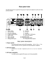
Take a look at the back panel of the AVP. You will notice that the RCA-type audio input
and output connectors are identified by colors. Red for right channel and white for the
left channel audio. Composite video input and output connectors are identified by
yellow. Digital inputs are identified by orange. The surround outputs are identified by
black. The audio inputs and outputs start at the center of the back panel and continue
to the right. The S-video inputs and outputs are located to the lower left side of the
preamplifier. The composite video inputs and outputs are above the S-video
connectors, to the left side of the back panel.
Audio only equipment
The procedure listed is for connecting a CD player to the AVP analog inputs.
Use the same instructions for connecting to the TUNER input.
1.
Attach one end of the audio interconnect cable to the left audio output on the CD
player, then attach the other end to the white left CD audio input on the AVP.
2.
Attach one end of the audio interconnect cable to the right audio output on the
CD player, then attach the other end to the red right CD audio input on the AVP.
Audio / Video source
The procedure listed is for connecting a DVD/VLD player to the AVP analog
inputs. Use the same instructions for connecting other audio / video sources to
the TV-V3 input.
1.
Attach one end of the audio interconnect cable to the left audio output on the
DVD/VLD player, then attach the other end to the white left DVD/VLD audio input
on the AVP.
2.
Attach one end of the audio interconnect cable to the right audio output on the
DVD/VLD player, then attach the other end to the red right DVD/VLD audio input
on the AVP.
3.
Attach one end of the composite video interconnect cable to the video out on the
DVD/VLD player, then attach the other end to the yellow video input on the AVP
labeled DVD/VLD.
Or
use the S-video connections.
The preamplifier will not
convert S-video to composite or composite to S-video.


