


The drivers can now be carefully lowered into place on the baffle. Having the terminals facing towards the bottom of
the cabinet is the generally accepted orientation, though it is not a critical matter. Using the included screws and pre-
drilled pilot holes, carefully tighten the drivers down onto the baffle. Pay particular attention to not over-tighten
screws on drivers with stamped steel or polymer frames, which can cause deformation of the flange.
5. Crossover Assembly Instructions
For the system to perform properly, it is important that the crossovers be assembled correctly. Incorrect assembly
can cause damage to the speaker drivers or your amplifier, so please take time to work carefully and to check your
work as you go.
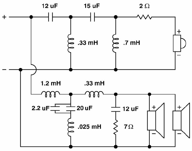
The crossover boards have a printed pictorial layout on them that includes an outline of the component and a part
label. Please refer to the parts list and schematic for a list of which components go in each location. Match the
component label from the description on the parts list to the label on the PC board.
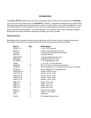
Indicator Description
C1/C4 Dayton DMPC-12 12uF 250V Polypropylene Capacitor
C2 Dayton DMPC-15 15uF 250V Polypropylene Capacitor
C3 Dayton DMPC-20 20uF 250V Polypropylene Capacitor
C5 Dayton DMPC-2.2 2.2uF 250V Polypropylene Capacito
r
L1 Jantzen 0.33mH 18 AWG Air Core Inductor
L2 Jantzen 0.70mH 18 AWG Air Core Inductor
L3 Jantzen 1.2mH 16 AWG Copper Foil Inductor
L4 Jantzen 0.025mH 18 AWG Air Core Inducto
r
L5 Jantzen 0.33mH 15 AWG Air Core Inductor
R1 Dayton DNR-2.0 2 Ohm 10W Non-Inductive Resistor
R2 Dayton DNR-7.0 7 Ohm 10W Non-Inductive Resistor