


Each component will have two leads that correspond to holes on the PC board. Put the components into place with
the leads going through their appropriate holes, following the pictorial on the board. Directionality on the components
is not important; either end of each component can go into either hole. It is recommended that each component be
secured to the board with hot-melt or silicone to prevent any possible vibration of components. Cable ties are
recommended on the inductors to hold them in place more firmly, especially if you are using silicone.
Once all of the components have been secured and have their leads going through the board, we can flip it over and
make the solder connections. To solder effectively, place the soldering iron tip so that it is touching both the
component lead and the PC board. This will allow both portions to heat simultaneously, and will ensure a good flow
of solder between the two. After heating the board and leads for several seconds, add solder to the joint to form an
effective connection. A good solder joint will have a conical shape, and will not look “blobby” or “spherical.”
On the inductors, make sure that the “silver” tinned section of the lead is what you are soldering to. Attempting to
solder to the copper-colored or red insulated portion of the inductor lead will result in a failed connection. After all
connections are made, the remaining component leads on the rear of the board can be trimmed down with a pair of
side cutters or other electrical cutters.
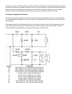
We can now solder the connecting wires (red/black zipcord) for the inputs and speaker terminals. Solder the input
wire from the binding posts to the woofer input, and solder a "jumper" wire from the woofer input to the tweeter input.
Then solder wire to the output crossover board terminals for woofers, and tweeter (W "+ ", W "-", T "+", and T "-").
Make sure that the positive terminals are connected to the positive (red) wires in all locations and allow ample length
of wire for connections.
Note:
Do not solder wire to the tweeter and woofer (speakers) at this time.
6. Test the speakers
At this point, it is recommended that you take some time to test the speakers before final installation of the
crossovers and baffles. You should already have the cabinets assembled and lined with foam, the drivers should be
in the baffles, and the crossovers should be assembled. Connect these three parts together to do a quick check that
everything is working correctly.
Note:
Temporary woofer and tweeter (speaker) connection will suffice for testing.
Place the crossover board into the cabinet in the approximate final location; it does not need to be secured right
now. Insert the baffle with the drivers on it into the cabinet, and secure with one or two of the baffle machine screws
if needed. If the baffle will stay in place on its own, it is not necessary to secure it.
Now, we need to connect the speakers to your stereo system. At this point we are not worrying about air leaks or the
bass response. We are just doing a quick check that the drivers and crossovers are working correctly.
Play music through the speakers and evaluate that the overall sound is full and smooth. Even though everything is
not completely secured, you should still be able to get a good idea of what the overall sound will be like. If a driver is
not working or the sound is intermittent or distorted, please see the troubleshooting section for possible remedies.
Be sure that you are satisfied that everything is working correctly before moving on to permanently installing the
crossover or baffle.