MPA 152 Amplier • Installation
Installation, cont’d
2-10
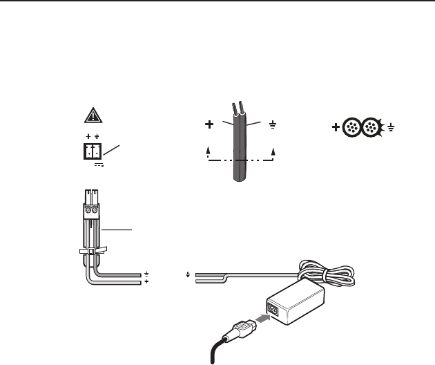
Power connector
Connect the two pole, 3.5 mm captive screw connector from
the power supply (provided) to this socket on the rear panel.
Ensure the connections have the correct polarity as shown in the
illustration below:
Power Receptacle
Power Supply
Output Cord
SECTION A–A
RidgesSmooth
A A
DC Power Cord
Captive Screw Connector
AC Power Cord
Ground
+12 VDC
External
Power Supply
(12 VDC, 3 A )
POWER
12V
3A MAX
Figure 2-6 — Connecting power
N
The length of the exposed wires in the stripping process
is critical. The ideal length is 3/16” (5 mm). Any longer
and the exposed wires may touch, causing a short circuit
between them. Any shorter and the wires can be easily
pulled out even if tightly fastened by the captive screws.
C
Do not tin the wires. Tinned wire does not hold its
shape and can become loose over time.


