3
US
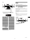
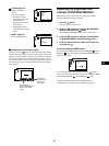
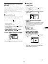
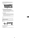
Identifying parts and controls
See the pages in parentheses for further details.
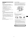
1 (input) switch (page 6)
This switch selects 1 (video input connector 1: 1 ) or 2
(video input connector 2: 2 ).
2 6m(contrast/down) and M (brightness/up)
buttons (pages 6 – 14)
These buttons are used to display the CONTRAST/BRIGHT
menu and to highlight the desired menu item.
3 button (pages 6 – 14)
This button is used to display the menu and to select the menu
item and to activated the adjustment.
4 </, buttons
(pages 6 – 14)
These buttons are used to make the adjustment.
5 ! (power) button and indicator (pages 5, 15, 17, 19)
This button turns the monitor on and off. The power indicator
lights up in green when the monitor is turned on, and lights up
in orange when the monitor is in power saving mode.
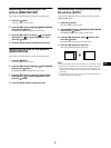
6 AC input connector (page 5)
This connector provides AC power to the monitor.
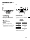
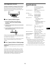
7 Video input connector 1 (HD15) (1 ) (page 4)
Inputs RGB video signals (0.700 Vp-p, positive) and sync
signals.
* Display Data Channel (DDC) Standard of VESA
AC IN
Front
Rear
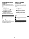
5 4 3 2
1
678910
1112131415
(continued)
Pin No. Signal
1Red
2Green
(Sync on
Green)
3Blue
4 ID (Ground)
5 DDC Ground*
6 Red Ground
7 Green Ground
Pin No. Signal
8 Blue Ground
9 DDC + 5V*
10 Ground
11 ID (Ground)
12 Bi-Directional
Data (SDA)*
13 H. Sync
14 V. Sync
15 Data Clock
(SCL)*