4
US
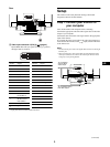
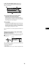
8 Video input connector 2 (DVI) (2 ) (page 4)
Inputs RGB video and sync signals (0.700 Vp-p, positive)
through a DVI-A connector.
* Display Data Channel (DDC) Standard of VESA
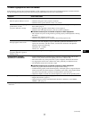
Setup
This monitor works with platforms running at horizontal
frequencies between 30 and 130 kHz.
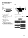
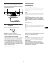
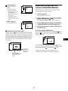
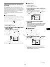
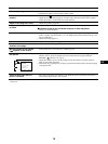
Step 1:Connect your monitor to
your computer
Turn off the monitor and computer before connecting.
Connect the appropriate end of the video signal cable to the video
output of your computer.
Connect the other end of the video signal cable to the appropriate
input of the monitor.
If you attach the video signal cable to the video input connector 1
on the back of the monitor, set the (input) switch on the front
of the monitor to 1.
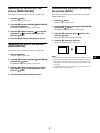
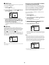
Notes
• Do not touch the pins of the video signal cable connector as this might
bend the pins.
• When connecting the video signal cable, check the alignment of the
video input connector. Do not force the video input connector in the
wrong way or the pins might bend.
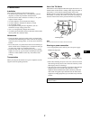
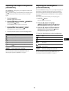
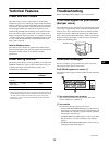
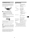
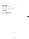
AC IN
Rear
87654321
C2 C1
C5
C4 C3
16 15 14 13 12 11 10 9
24 23 22 21 20 19 18 17
Pin No. Signal
C1 Red
C2 Green
C3 Blue
C4 H. Sync
C5 Ground (R/G/B)
1 —
2 —
3 —
4 —
5 —
6Data
Clock(SCL)*
7 Bi-Directional
Data (SDA)*
8 V.Sync
9 —
Pin No. Signal
10 —
11 —
12 —
13 —
14 DDC + 5V*
15 Ground
16 Hot Plug Detect
17 —
18 —
19 —
20 —
21 —
22 —
23 —
24 —
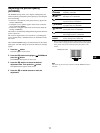
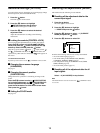
AC IN
To a computer with a
DVI video output
forward side
forward side
backward side
backward side
To a computer
with an HD15
video output
(continued)