


Solutions to Common Problems
9
Problem:
Serial communication doesn’t work correctly.
Solution:
Are the serial devices connected properly? Are the serial
parameters correct for source/destination devices?
Are the serial cables terminated correctly? If a null-modem cable
is used, it must be placed at the receiver end.
When using RS-232 transmitters or receivers in daisy chains, CAT
5 switches or CAT 5 distribution amps, the serial signal is a
unidirectionally broadcast mode only. In this mode, all other
Cobra CAT 5 Video System devices must be the simplex serial
type.
The last device in a transmitter-to receiver or daisy chain
configuration must be terminated. The R1300A can be used as
either a “middle unit” or an “end unit”; the termination switch is
located on the front of the unit.
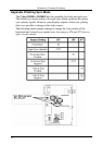
Problem:
“Green shift” or “green washout” on multimedia signals.
Solution:
The standard video/serial model is designed to function with DC
coupled signals in which the black level is referenced to 0 volts.
Nearly all VGA cards function this way. Some media servers,
however, provide AC coupled signals and can cause a green color
shift in the video. This is a result of the sync clamping on the red
and blue channels of the video/serial model. For five-component
(RGB/H&V) AC coupled video, the Cobra CAT 5 transmitter has
been designed with full DC restoration capability. This problem is
easily solved via a simple switch setting in the Cobra Transmitter.
Refer to the Cobra Transmitter user manual.
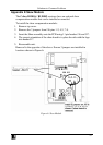
Problem:
Notes on Daisy Chaining:
Solution:
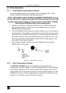
When daisy chaining, the maximum cable distance is not
increased beyond the rated distance of the receiver used. For
example, the maximum distance from a transmitter to the last
R1300S2 Receiver in a daisy-chain is 1300 feet. . If a unit in the
middle of the chain loses power or is disconnected from the chain,
all units after this will lose signals. All serial communication in a
daisy chain is one way simplex.