


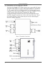
KRAMER: SIMPLE CREATIVE TECHNOLOGY
Solutions to Common Problems
10
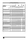
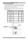
Appendix A Cabling Pinouts
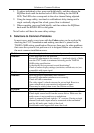
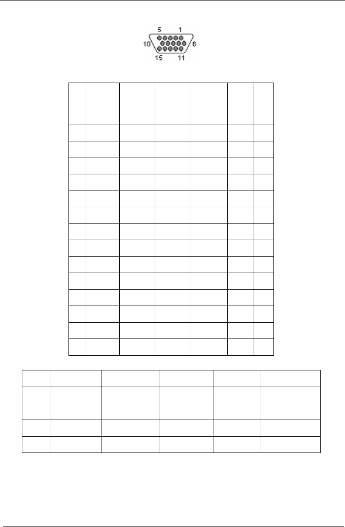
Table 1: HD15 Video Connector PINOUT
Pin RGBHV
(VGA)
RGBS RGsB Composite
SVHS
(Y/C)
YUV
1 Red + Red + Red + C+ V+
2 Green+ Green+ Green+ C+ Y+ Y+
3 Blue+ Blue+ Blue+ U+
4 — — —
5 Gnd Gnd Gnd
6 Red- Red- Red- C- V-
7 Green- Green- Green- C- Y- Y-
8 Blue- Blue- Blue- U-
9 — — —
10 Gnd Gnd —
11 Gnd Gnd —
12 — — —
13 H Sync C Sync —
14 V Sync — —
15 Gnd Gnd —
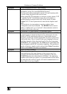
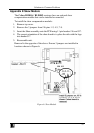
Table 2: Terminal Block Connection
PIN Audio Audio* Simplex Serial S/PDIF Audio
Composite Video
Pin 1 Left Channel Right Channel Tx Signal + Signal +
Pin 2 Ground Ground ground Signal - Signal -
Pin 3 Right Channel Left Channel - - -
Pin 4 - Shell - -
Note: Typically Channel 1 is left audio and Channel 2 is right audio.
* series RECEIVER units use Channel 1 for Right audio and channel 2
for left audio.
* series TRANSMITTER units use Channel 2 for Right audio and channel
1 for left audio.