


12 VA-8xl - Controlling the VA-8xl
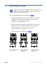
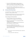
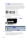
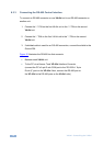
Method B (Figure 8)—Connect the RS-232 9-pin D-sub port on the unit via a
straight (flat) cable to the null-modem adapter, and connect the null-modem
adapter to the RS-232 9-pin D-sub port on the PC. The straight cable usually
contains all nine wires for a full connection of the D-sub connector. Because the
null-modem adapter (which already includes the flow control jumpering described
in Method A above) only requires pins 2, 3 and 5 to be connected, you are free to
decide whether to connect only these 3 pins or all 9 pins.
Figure 8: Straight Cable RS-232 Connection with a Null Modem Adapter
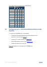
6.2.1 DIP-Switch Settings
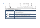
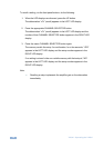
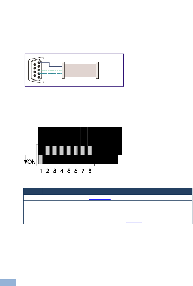
Configure the VA-8xl by setting the DIP-switches as defined in Figure 9:
Figure 9: Rear Panel DIP-switches (Factory Default)
DIP # Function:
1-4 Set the MACHINE # (see Section 6.2.2)
5 Not used
6 RS-485 termination for first and last machine = ON (RS-485 line terminates with
110Ω); for others = OFF (RS-485 line is open)
7/8 Used for the firmware upgrade procedure (see Section 7)
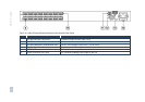
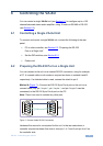
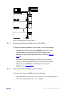
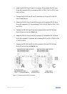
6.2.2 Setting the MACHINE #
To control a unit via RS-232 or RS-485, each unit has to be identified via its
unique MACHINE #. Set the MACHINE # on a VA-8xl unit according to the
following table. A valid MACHINE # is from 1 to 15.
1
2
6
3
7
4
8
5
9
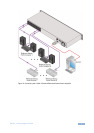
to PC
Null-Modem
Adapter