


4
ENGLISH
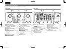
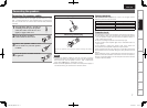
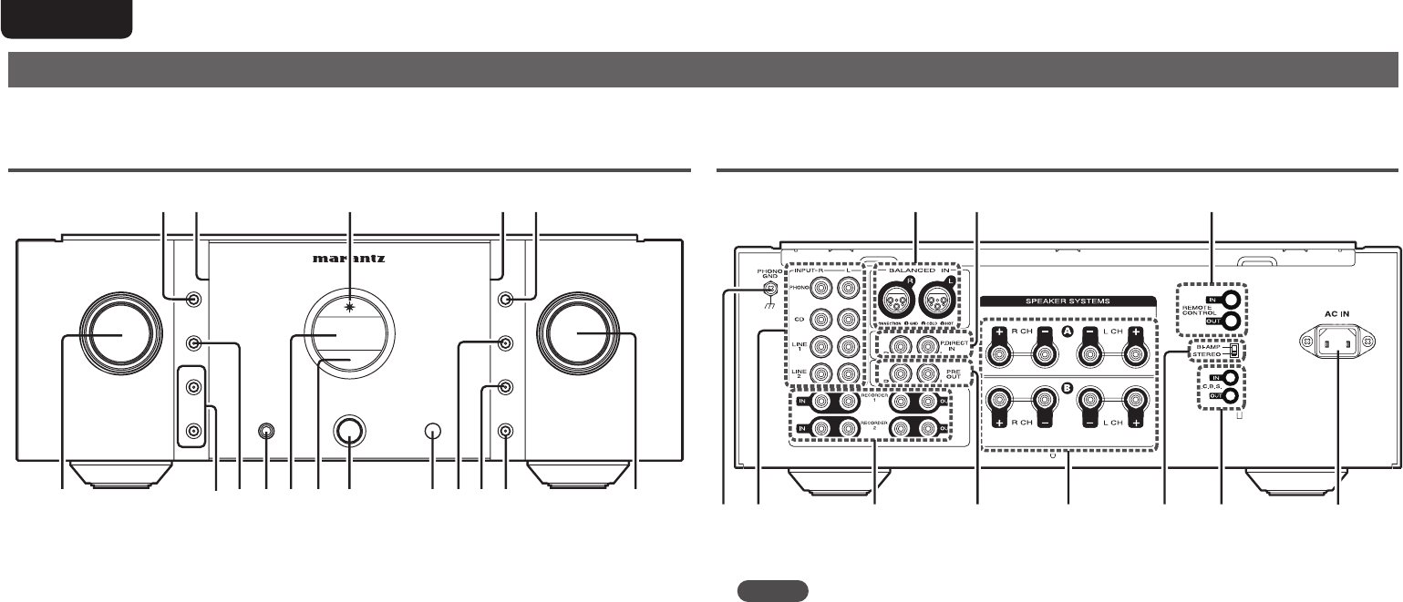
Part names and functions
For buttons not explained here, see the page indicated in parentheses ( ).
q INPUT SELECTOR knob ·····················(11)
w Speaker output switch button
(SPEAKERS A, SPEAKERS B) ············ (11)
e TONE button ······································(12)
r Headphone jack (PHONES) ··············· (13)
t Display
y Standby status indicator
Indicates the status of the unit’s as follows:
•Power “ON” ....................................... Off
•Standby .............................................. Red
•Power “OFF” ......................................Off
u Power switch (X ON/OFF) ················ (11)
i Remote control sensor ························ (2)
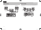
o PRE OUT switch button ···················· (19)
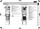
q PHONO GND (ground) terminal ·········(9)
NOTE
This terminal is not a safety ground.
w Input terminals (INPUT) ······················(9)
e Input/output terminals (Recordings)
(RECORDER1, RECORDER2) ··············(10)
r PRE OUT terminals ···························· (19)
t Speaker system terminals
(SPEAKER SYSTEMS) ······················(7, 8)
Q0 Power amplifier direct mode switch
button (P.DIRECT IN) ·························(19)
Q1 Phono equalizer switch button
(PHONO MC) ·········································(9)
Q2 VOLUME knob ····································(11)
Q3 Attenuator button (ATT.) ·················· (13)
Q4 Illumination lamp ·······························(13)
Q5 Power indicator ··································(11)
Indicates the status of the unit’s as follows:
•Power “ON” ..................................... Blue
•Standby ...............................................Off
•Power “OFF” ......................................Off
Q6 DISPLAY button ·································(13)
Front panel
X ON/OFF
PHONES
VOLUME
A
TONE
SPEAKERS
B
SPEAKERS
PRE OUT
ATT.
MC
PHONO
IN
P.DIRECT
DISPLAY
SELECTOR
INPUT
INTEGRATED AMPLIFIER PM-11S3
STANDBY
qyuiQ11 Q22
Q3Q4
Q4Q5Q6
wert oQ0
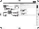
Rear panel
3
1
2
3
1
2
w
e
r
Q0
y
t
ui
q
oQ1
y Amplifier mode switch ······················ (16)
u F.C.B.S. terminals ·······························(14)
i AC inlet (AC IN) ·································· (10)
o REMOTE CONTROL terminals ·········· (20)
Q0 Power amplifier direct terminals
(P. DIRECT IN) ·····································(19)
Q1 Balanced input terminals ···················· (9)
1.PM-11S3U_ENG_0521.indd 4 2012/05/21 19:03:28