


Contents
© National Instruments Corporation ix NI-DSP SRM for LabVIEW for Windows
Figures
Part 1
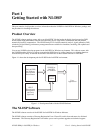
Figure 1-1. Development Paths with the NI-DSP Software ............................................................................. 1-1
Part 2
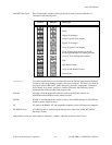
Figure 1-1. Communication between the PC and the DSP Board .................................................................... 1-1
Figure 1-2. DSP Handle Cluster ....................................................................................................................... 1-3
Figure 1-3. The Hexadecimal Encoding of a Typical DSP Handle.................................................................. 1-3
Figure 1-4. Front Panel–An Example of How to Allocate a DSP Handle Cluster........................................... 1-4
Figure 1-5. Block Diagram–An Example of How to Allocate a DSP Handle Cluster..................................... 1-4
Figure 1-6. DSP Add VI ................................................................................................................................... 1-5
Figure 1-7. The error in/error out Cluster...................................................................................................... 1-5
Figure 1-8. An Example That Does Not Use error in/error out for Sequencing VIs .................................... 1-6
Figure 1-9. An Example of Using the error in/error out Cluster for Sequential VI Execution..................... 1-7
Figure 1-10. Front Panel–An Example of Using NI-DSP Analysis VIs ............................................................ 1-8
Figure 1-11. Block Diagram–An Example of Using NI-DSP Analysis VIs ...................................................... 1-8
Part 3
Figure 1-1. Choosing DSP2200 from the Functions Menu .............................................................................. 1-4
Figure 1-2. Spectral Leakage Demonstrated Using Convolution..................................................................... 1-7
Part 4
Figure 1-1. NI-DSP for DOS Directory Structure ............................................................................................ 1-1
Figure 1-2. Interface Layers to Onboard Functions.......................................................................................... 1-2
Figure 2-1. Linker File NIDSPLNK................................................................................................................. 2-4
Figure 2-2. Library Function List File NIDSP.fnc ........................................................................................... 2-4
Figure 2-3. Typical Section of NIDSP.fnc ....................................................................................................... 2-5
Figure 2-4. Signals Group Section in dspfncs.h ............................................................................................... 2-6
Figure 2-5. Signals Group Section in dispatch.s............................................................................................... 2-6
Figure 2-6. How to Bundle Parameters in LabVIEW to Call gmaxmin.c ........................................................ 2-9
Figure 2-7. How to Connect to Custom VI to Call gmaxmin.c ........................................................................ 2-10
Figure 2-8. Block Diagram–How to Index the Output Arrays of the Custom VI ............................................ 2-11
Figure 2-9. Block Diagram–Using the Custom VI to Call gmaxmin.c on theDSP Board from LabVIEW..... 2-11
Figure 2-10. Front Panel–Using the Custom VI to Call gmaxmin.c on theDSP Board from LabVIEW........... 2-12