


26
English
CY-VM7203W
27
English
CY-VM7203W
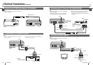
Installation
25 26
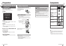
Preparation
Caution
Please follow the laws and regulations of your
province or country for installation of the unit.
When bending the mounting tab of the mounting
collar with a screwdriver, be careful not to injure
your hands and fi ngers.
We strongly recommended you to wear gloves for
installation work to protect yourself from injuries.
Disconnect the cable from the negative () battery
terminal (see caution below).
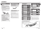
The unit should be installed in a horizontal position with
the front end up at a convenient angle, but not more
than 30.
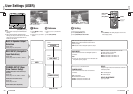
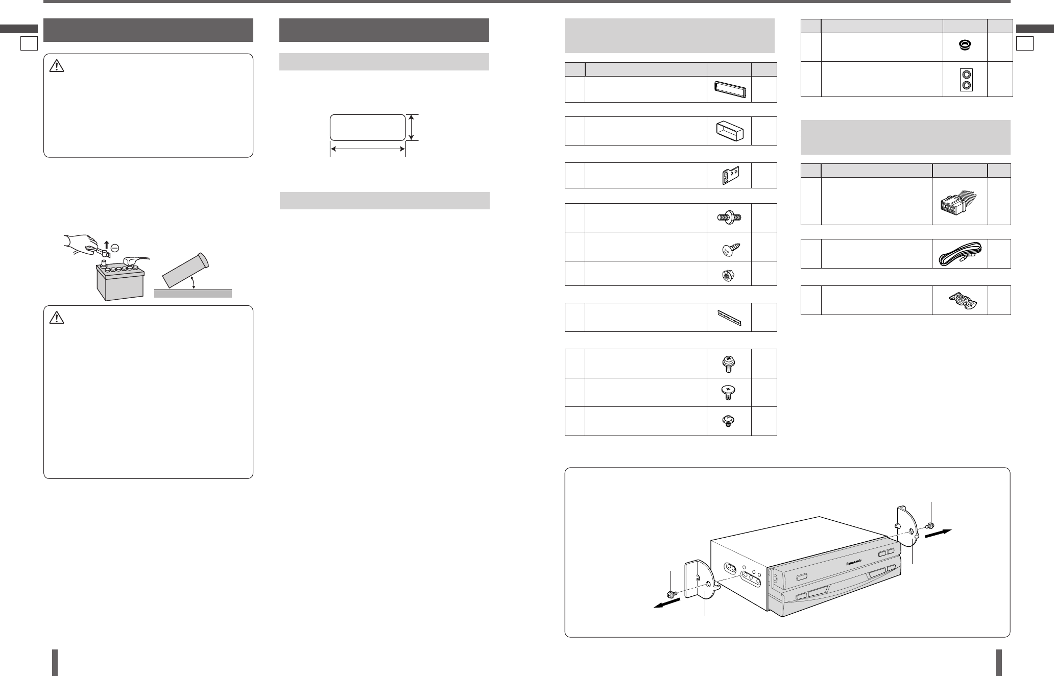
Installation Opening
This unit can be installed in any dashboard having an
opening as shown below. The dashboard should be 4.5
mm–6 mm thick in order to be able to support the unit.
53 mm
182 mm
Caution
If your car is equipped with air bag and/or anti-
theft systems specifi c procedures may be required
for connection and disconnection of the battery to
install this product.
Before attempting installation of this electronic
component contact your car dealer or
manufacturer to determine the required procedure
and strictly follow their instructions.
FAILURE TO FOLLOW THE PROCEDURE MAY
RESULT IN THE UNINTENDED DEPLOYMENT OF
AIR BAGS OR ACTIVATION OF THE ANTI-THEFT
SYSTEM RESULTING IN DAMAGE TO THE VEHICLE
AND PERSONAL INJURY.
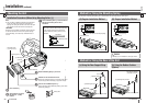
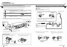
Dashboard Installation
Installation Precautions
This unit should be installed by a professional installer.
In case of diffi culty, please consult your nearest
authorized Panasonic Service Center.
This system is to be used only in a 12 V DC battery
system (car) with negative ground.
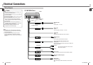
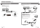
Follow the electrical connections carefully (page 32).
Failure to do so may result in damage to the unit.
Connect the power lead after all other connections are
made.
Be sure to connect the battery lead (yellow) to the
positive terminal () of the battery or fuse block (BAT)
terminal.
Insulate all exposed wires to prevent short circuiting.
Secure all loose wires after installing the unit.
Please carefully read the operating instructions of the
respective equipment before connecting it to this unit.
030
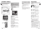
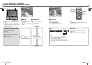
Installation Hardware
(For Installation)
No. Item Diagram Qty.
Trim Plate 1
(YFC054C087CA)
Mounting Collar 1
(YFX214C433CA)
Mounting Spring 2
(YFX054C077CA)
Mounting Bolt (5 mm) 1
Tapping Screw
(5 mm16 mm)
1
Hex. Nut (5 mm) 1
(ZZBISVD7001A)
Rear Support Strap 1
(YFG044C002ZA)
Round Head Screw
(5 mm6 mm)
2
Flat-Head Screw
(5 mm6 mm)
4
Round Head Screw
(4 mm3 mm)
4
(ZZBISVD7001B)
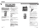
Transportation Bracket Removal
Be sure to remove the transportation brackets before use
(installation). Use screws (5 mm6 mm) with washers for
installation.
Be careful not to lose these screws.
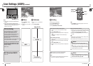
Installation Hardware
(For Wiring)
Note:
The number in parenthesis underneath each accessory
part name is the part number for maintenance and
service.
Accessories and their parts numbers are subject to
modifi cation without prior notice due to improvements.
Use the supplied screws for installation exclusively. In
case of losing any of them, please order the specifi c
screw.
No. Item Diagram Qty.
Power Connector 1
(YAJ024C119CA)
Reverse Extension Cord 1
(WAVS05M6000T)
Clip Connector 1
(YEAT034C012)
Round Head Screw
(5 mm6 mm)
Transportation Bracket
Round Head Screw
(5 mm6 mm)
Transportation Bracket
No. Item Diagram Qty.
Spacer 2
Double-Faced Adhesive Tape 1 set
(ZZBISVD7001E)