


[
4
]
Pelco Manual C1506M (3/00)
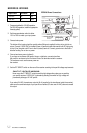
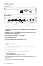
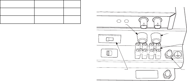
ERD2200 WIRING
ERD2200 Power Connections
ENCLOSURE
POWER OUT
L
L
N
N
115V
230V
115V
POWER
SELECTOR
SWITCH
GROUND
STUD
POWER
TERMINALS
MAIN
FUSE
ENCLOSURE FUSE
MAIN
POWER IN
1. Fuses are installed for 115 VAC operation.
For 230 VAC operation, install the appropriate
fuses (supplied).
2. Set the power selector switch to either
115V or 230V to match your input power.
3. Connect main power.
Input Power Enclosure Main
115 VAC 4A .5A
230 VAC 2A .25A
PAN/TILT VOLTAGE WARNING:
Never move the P/T SELECT switch toward the high voltage side unless you are positive
your pan/tilt requires 115/230 VAC. Inadvertently selecting the switch for high voltage will
permanently damage a 24 VAC pan/tilt.
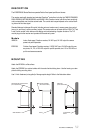
The bottom of the housing has five conduit entries (fittings not supplied) to bring wiring into the re-
ceiver. Connect 115/230 VAC to the Main Power In terminals inside the receiver with AC high going
to the L (line) terminal and AC low to the N (neutral) terminal. Connect ground wire to the stud in-
side the housing. Do not turn on power.
4. Connect enclosure power (optional).
If you have an enclosure with heater, blower, or defroster, connect wires from
the pan/tilt or enclosure to the Enclosure Power Out terminals inside the receiver.
The enclosure must use the same power as
the receiver.
5. Set the P/T SELECT switch on the rear of the receiver according to the pan/tilt voltage requirements.
If you select 24 VAC, the maximum output is 48 vA (supplied by the transformer inside the receiver);
make sure the combined output of your pan/tilt and camera (if it also uses 24 VAC) does not exceed
this output.