


Pelco Manual C1506M (3/00)
[
9
]
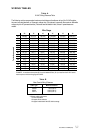
Wire Gauge
Table A
24 VAC Wiring Distances Table
The following are the recommended maximum wire distances (transformer to load) for 24 VAC applica-
tions and are calculated with a 10-percent voltage drop. (Ten percent is generally the maximum allowable
voltage drop for AC-powered devices.) Distances are calculated in feet; values in parentheses are
meters.
20 18 16 14 12 10
10 283 (86) 451 (137) 716 (218) 1,142 (348) 1,811(551) 2,880 (877)
20 141 (42) 225 (68) 358 (109) 571 (174) 905 (275) 1,440 (438)
30 94 (28) 150 (45) 238 (72) 380 (115) 603 (183) 960 (292)
40 70 (21) 112 (34) 179 (54) 285 (86) 452 (137) 720 (219)
50 56 (17) 90 (27) 143 (43) 228 (69) 362 (110) 576 (175)
60 47 (14) 75 (22) 119 (36) 190 (57) 301 (91) 480 (146)
70 40 (12) 64 (19) 102 (31) 163 (49) 258 (78) 411 (125)
80 35 (10) 56 (17) 89 (27) 142 (43) 226 (68) 360 (109)
90 31 (9) 50 (15) 79 (24) 126 (38) 201 (61) 320 (97)
100 28 (8) 45 (13) 71 (21) 114 (34) 181 (55) 288 (87)
110 25 (7) 41 (12) 65 (19) 103 (31) 164 (49) 261 (79)
120 23 (7) 37 (11) 59 (17) 95 (28) 150 (45) 240 (73)
130 21 (6) 34 (10) 55 (16) 87 (26) 139 (42) 221 (67)
140 20 (6) 32 (9) 51 (15) 81 (24) 129 (39) 205 (62)
150 18 (5) 30 (9) 47 (14) 76 (23) 120 (36) 192 (58)
Total vA consumed
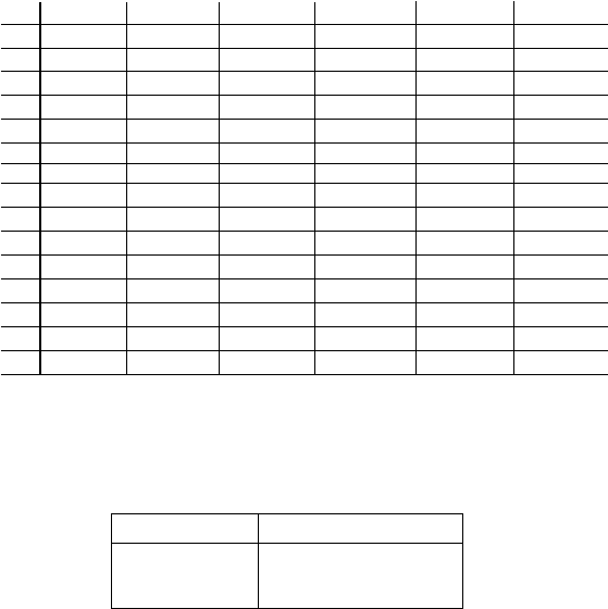
Table B
Video Coaxial Wiring Distances
Cable Type* Maximum Distance
RG59/U 750 ft (229 m)
RG6/U 1,000 ft (305 m)
RG11/U 1,500 ft (457 m)
EXAMPLE: An enclosure that requires 80 vA and is installed 35 feet (10 m) or less from the 24 VAC source
would require a minimum wire gauge of 20 AWG.
* Minimum cable requirements:
75 ohms impedance
All-copper center conductor
All-copper braided shield with 95% braid coverage
WIRING TABLES