


[
8
]
Pelco Manual C1506M (3/00)
FUSE REPLACEMENT
IRD2024
Lens/Auxiliary Fuse – A 500 mA fuse protects the LENS and AUX 1 outputs. Remove the cover
of the receiver to check the fuse.
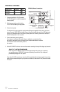
ERD2200
Main Fuse – The main fuse protects the pan/tilt output when 24 VAC pan/tilt operation is selected. It
also protects the 24 VAC camera output. Refer to the
ERD2200 Wiring
section for fuse location and values.
Enclosure Fuse – The enclosure fuse protects the pan/tilt output when 115/230 VAC pan/tilt op-
eration is selected. It also protects the enclosure output. Refer to the
ERD2200 Wiring
section for fuse lo-
cation and values.
Lens/Auxiliary Fuse – A 500 mA fuse protects the LENS and AUX 1 outputs. Remove the cover
of the receiver inside the housing to check the fuse.
TROUBLESHOOTING
Check the wiring connections.
If the CX LED does not blink when commands are sent to the receiver, make sure the controller is work-
ing properly. Also check the video coaxial cable between the controller and the VIDEO OUT connection
on the receiver.
An LRD41TLC Test Local Control Module is available from Pelco to test or troubleshoot your receiver,
pan/tilt, and lens functions directly from the receiver.
This lightweight, hand-held keypad tests the up, down, left, and right functions of the pan/tilt, and the iris
open/close, focus near/far, and zoom telephoto/wide functions of the lens.
1. Plug the module into the TLC connector on the front of the receiver. The module can be plugged in
with the receiver’s power turned on.
2. Push the buttons on the keypad to test your equipment. The TLC module can be used without discon-
necting the receiver from the controller. The TLC module will override any signals from the controller.