


Pelco Manual C1506M (3/00)
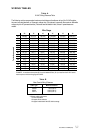
[
5
]
6. Connect the pan/tilt controls (up, down, left, right, and common).
7. Connect the camera power.
If your camera uses 24 VAC, connect the camera to the CAM PWR connector on the front of the re-
ceiver. The camera’s power must not exceed 5 vA.
If your camera uses 115 or 230 VAC, connect the camera’s power leads to the Enclosure Power Out
terminals inside the receiver. The camera’s power must be the same as the receiver’s power (Main
Power In terminals).
8. Connect the motorized lens controls (iris, focus, zoom, and common).
9. Connect video.
VIDEO IN comes from the camera.
VIDEO OUT goes to the controller.
If necessary, refer to Table B in the
Wiring Tables
section to determine appropriate coaxial cable types
for video applications.
10. Connect the auxiliary outputs (optional).
AUX 1 is a 5 VDC, 20 mA maximum, open collector output. Use the auxiliary:
• To operate low current relays
• To turn on or off a Pelco window wiper that has TTL circuitry
AUX 2 is a normally open/normally closed (Form C) relay. Relay contacts are rated at 1A maximum at
24 VDC or .5A maximum at 115 VAC.
11. Double check all wiring connections, and then turn on power.
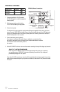
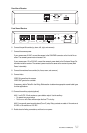
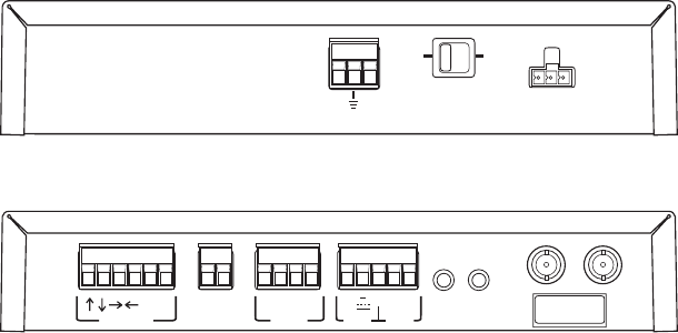
Front View of Receiver
24V
AC
PAN/TILT CAM PWR
I F Z C
LENS
AUX1 AUX2
5V
CNN
CO
PWR CX
IN OUT
VIDEO
TLC
CC
~
+
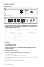
Rear View of Receiver
24 V
AC
INPUT
ERD OPTION
P/T SELECT
115/230
V
AC
24 V
AC
~
~
~