


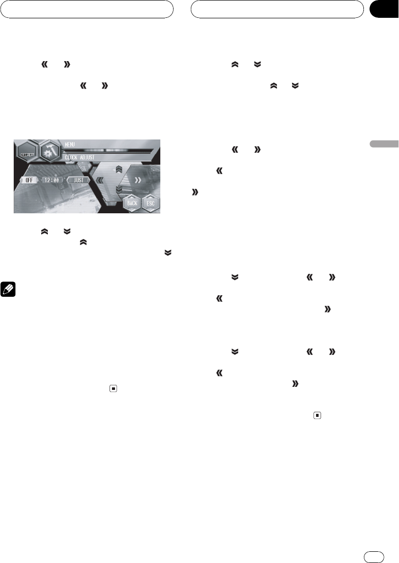
3 Touch or to select the segment of
the clock display you wish to set.
Each time you touch
or it will select one
segment of the clock display:
HourMinute
As you select segments of the clock display
the segment selected will be highlighted.
4 Touch or to set the clock.
Each time you touch
it increases the se-
lected hour or minute. Each time you touch
it decreases the selected hour or minute.
Notes
! You can match the clock to a time signal by
touching JUST.
If the minute is 0029, the minutes are
rounded down. (e.g., 10:18becomes
10:00.)
If the minute is 3059, the minutes are
rounded up. (e.g., 10:36 becomes 11:00.)
! Even when the sources are off, the clock dis-
play appears on the display.
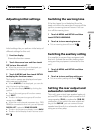
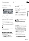
Setting the display
appearance
Touch panel key color, background picture and
motion text can be changed.
1 Touch A.MENU and SETUP and then
touch APPEARANCE.
2 Touch
or to select the desired
item.
Each time you touch
or selects the item
in the following order:
TOUCH KEY COLOR (touch panel key color)
BACKGROUND PICTURE (background pic-
ture)MOTION TEXT (motion text setting)
3 Touch
or to select the touch panel
key color.
Touch
to select the touch panel key color
blue and BLUE appears in the display. Touch
to select the touch panel key color silver
and SILVER appears in the display.
# Changing the touch panel key color switches
the skin of the SPEANA1 (spectrum analyzer1)
and LEVEL METER2 (level meter2). (Refer to
Switching the background display on the next
page.)
4 Touch and then touch or to se-
lect the back ground picture.
Touch
to select background picture 1 and
BGP1 appears in the display. Touch
to se-
lect background picture 2 and BGP2 appears
in the display.
5 Touch
and then touch or to se-
lect the motion text setting.
Touch
to select motion text off and OFF ap-
pears in the display. Touch
to select motion
test on and ON appears in the display.
# When the vehicles parking brake is notde-
tected, motion text is not activated.
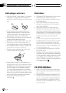
Using the AUX source
An IP-BUS-RCA Interconnector such as the
CD-RB20/CD-RB10 (sold separately) lets you
connect this unit to auxiliary equipment fea-
turing RCA output. For more details, refer to
the IP-BUS-RCA Interconnector owners man-
ual.
Other Functions
En
95
Section
18
Other Functions