


XR-P740M,
XR-P64()M,
XR-P340M
xR-P7 44, XR-P640, XR-P34()
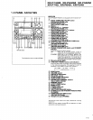
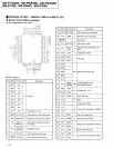
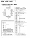
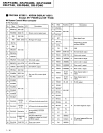
a
Pin
Function
of
Power Amo
Module
Connector
No.
Name UO
Description
cN7l01
+ 12V.
M o
+
12V separate system stabilized output
2 UNREG
12 Unstabilized
power
input for
-
12V
3
AC I AC detecrion input: for
power
ON/OFF and MUTE.
4
tzv o Stabilized
power
output for
-
12V
5 MUTE
vo Mute external input; outputs intemal mut€ conditions; cancels forced mute.
6 REF, GND I GND
Ior
protective
circuit;
reference GND for
short detection
7 BLOW I BLOW circuit extemal output; ON at
:t0.5V
or mo!e.
8 REG. GND I Reference GND for stabilized
power
source
9 UNREG
+5
I Unstabilized
power
input for
+5.6V
10 UNREG
+
12 I Unstabilized
power
input for
+12V
and
+12V.
M
11
+5.6V
o
+5.6V stabilized output
T2
+t2v
o
+
12V
stabilized output
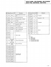
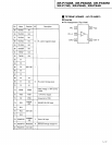
cN7l02
1 CIN I Center signal input
2 S. GND I Signal input GND; floating interior type
3 srN
I Surround signal input
4 OVERLOAD I Short
detection input for Surround and Center channels
5
+82
I Power supply
(+)
for Surround and Center channels
6
82 I Power supply
(-)
for Surrcund and Center channels
7 C OUT
o Center speaker output
8 S OUT o
Surround speaker output
cN7502
I REF. GND I Reference
GND lor short detection
2 L OUT o Left speaker
output
3
R
OUT o
Right speaker output
4 FAN I
Forced fan circuit input
(LOW
speed)
5
+81
I
Power supply
(*)
for L/R channels
6 B1
Power supply
(
)
for L/R channels
7
SHORT Short detection
input for I-./R channels
8 LIN
Left signal input
9 F. GND
Signal input GND; floating interior type
10
RIN Right signal
input