


XR-P7@M,
XR-P64OM,
XR-P3@M
xR-P7
40, XR-P64(),
XR-P34()
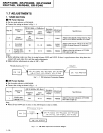
1.7
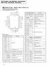
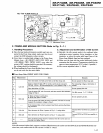
ADJUSTMENTS
1. TUNER
SECTION
I
FM Tuner
Section
a
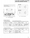
Set the mode
selector to
FM BAND.
a
Connect
the wiring
as shown in
Fig. I
1.
o
Before
adjusting,
make sure there is
no
gap
between
L6101 and L6102.
If there is
a
gap
between them,
bing them into
contact with
each other first,
and then make
adjustments.
o
Make
indicator adjustments
in order of AM
-
FM.
FM75 Q Anrenna
Te.minat
la;?n1
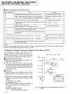
Fig.
1- 1 FM Adjustmont
Connection Diagram
I
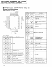
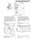
AM
Tuner
Section
a
Set
the mode selector
to AM
BAND.
a
Conoect the wiring
as shown
in Fig. I 2.
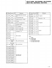
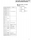
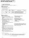
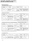
Step No.
Adjustment
Title
FM SG
(lkHz,
t
75kHz dev.)
Reception
Frequency
Display
Adjustment
Location
Specifications
Frequency
(MHz)
Level
(dBpV)
I
Center
Adjustment
98
Non
modulation
80 or
more
L6207
Adjust
so that the DC voltage
befween
Pin 4
and Pin 28
of IC6201 becomes
0Vt50mV.
2
Front
End
Sencitivity
98
l0- 30
98MHz
L6102
T6101
Adjust so
that the DC voltage of
the Pin12 of
IC6201
(S-meter)
becomes at maximum
level.
3
TUNED
IND.
Lighting
Level
98
lfi.2 98MHz
vR6201
Adjust
so that the indicators
ot TUNED
IND. start
to light up.
Nofes.'
IC5201
XR_P74OM,
XR_P54OM,
XR_P
34M
xR-P740,
XR-P640.
XR-P340
DC
VOLTMETER
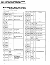
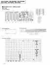
Step
No.
Adjustment
Title
AM SG
(400H2,
3070 Mod.)
Reception
Frequency
Display
Adjustment
Location
Specifications
Frequency
(kHz)
Level
(dBpY,h)
I
TUNED
IND.
Lightirg
Level
999
47 !2
999kHz
vR6202
Adjust
so that the indicators
of TUNED
IND. start
to light up.
Note.'
a
When SD
and YPW type is
used, set
the AM Irequency
step to 10kHz.
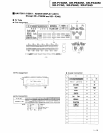
A M
An renna Ter.m
r na l
XR_P74OM,
XR_P64OM,
X R_P
34M
xR-P740,
xR-P54
0. XR-P340
AM
Loop Antenna
1-20
Fig,
1-2 AM
IMW)
Adjuslment
Connection Diagram