


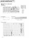

XR-P740M,
XR-P64()M,
XR-P34()M
xR-P7
Q, XR-P64(), XR-P34()
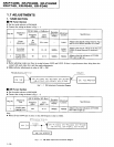
Step
Tap€
Selector
(AUTO)
Mode
Input
Signaf
Test Tape
Adjusting Points
Measuement
Poiots
Adjustment
Value
Remarks
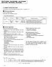
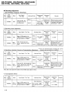
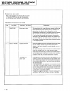
NORMAL REC
Load the STD 631
test
tape and set the
recording mode.
Deck
I
Oscillation fre-
quency
to be
105.0kH2
t2kHz.
When the
pori.er
is tumed
ON while
the
BAND buttol
is depressed, the frequency
will decrease 2
3 kHz.
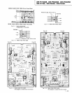
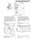
Deck tr
Between
@
point
in Fig.
3-4 and GND.
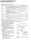
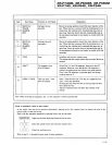
O
Recording
Adiustmont
1 . Bias
Oscillation Frequency Adiustment
3.
Recording/playback Frequency
Characteristics Adjustment
a Since
this
adjustment
aJfects recording bias,
prevent
distortion Irom increasingdue to underbias.
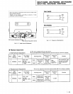
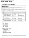
2. Recording Level
Adjustment
Step
Tape
Selecto!
(AUTO)
Mode Input Sigrral/Test Tape Adjusting
Points
Measurement
Points
Adjustment
Value
Remarks
1 NORMAL REC
Input
a 315H2 signal to the
VIDEOiAUX IN terminal and set
the input selector to VIDEO.
Deck
I
Input signal
level
TAPE TEST
POINT
(L,
Rch)
(AF
CD Assy)
5.2 dBV
Deck
II
2
NORMAL
REC,,
PLAY
STD 631 test tape and
record,
"playback
the 315H2
signal.
Deck
I TAPE TEST
POINT
(L,
Rch)
(AF
CD Assy)
Repeat recording,
playback
and adjustment until
playback
level of the 315H2
signal becomes 5.2dBV.
Deck tr
vR4301
vR4302
(Lch)
(Rch)
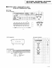
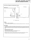
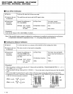
Step
Tape
Selector
(AUTO)
Mode Input Signal/Test Tape Adjusting Points
Measurement
Points
Adjustment
Value
Remarks
L NORMAL REC
Input a 315H2 siSnal to the
VIDEO/AUX IN terminal
and set
the input selector to VIDEO.
Deck
I
TAPE TEST
POINT
(L,
Rch)
(AF
CD Assy)
25.2 dBy
Deck
II
Input
signal
level
2 NORMAL
REC,,'
PLAY
Load the STD
-631
test tape and
record/playback
the 315H2 and
10kHz signals.
(see
the Note
below)
Deck
I
TAPE TEST
POINT
(L,
Rch)
(AF
CD Assy)
Repeat
adjustment until
playback
level of the 10kHz
signal is vrithin 0 t0.5dB
from that of the 315H2
signal.
Deck tr
VR4351
(I-ch)
VR4352
(Rch)
Note; Set to the same level used for the 315H2 input signal at step 1.
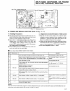
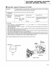
4.
ALC Operation Check
Step Selector
(AUTO)
Mode Input Signal/Test Tape Adjusting Points
Measutement
Points
Adjustment
Value
Remarks
I
NORMAL
REC
.
PAUSE
Input a 315H2 signal to the
VIDEO/AUX IN
terminal and set
the input selector to VIDEO.
Input siSnal level
TAPE TEST
POINT
(L,
Rch)
(AF
CD Assy)
-5.2
dBV
2
Set to a level
+
10dB
above the input level at
step 1.
2.h.2.5d8y
1- 26