


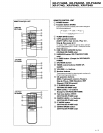


XR-P740M, XR-P640M,
XR-P34()M
xR-P7
40,
XR-P64trJ_,
XR-P340
1.6
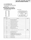
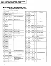
IC INFORMATION
c
The information
shown in the
list is basic information
and
may not correspond exactly
to that shown
in
the
schematic diagrams.
I
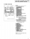
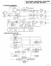
rc9268F
ilc84o1
: AF cD AssY)
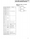
O X-A
Modulation-Type
DA Converter
with
Built-in 8-fold Oversampling
Digital Filter
o
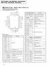
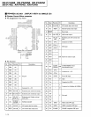
Pin Assignment
(Top
View)
o
Block Diagram
LrcX
rcK
EF
WA
-
WX
xo
XI
NX
LrcK MX MTA K EF rcK WX
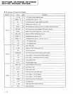
o
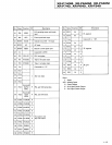
Pin Function
No. Symbol
VO
Description
Remarks
I VDD Digital
part power
supply terminal
2
T1
I
Test terminal; normally
used on
"L"
GNDA Analog
part ground
terminal for R channel
4 RO o R channel data right output
terminal
RO
o R channel data inverse output
terminal
6
VDA Analog
part power
supply
terminal
7 LO o
L channel data inverse output terminal
8 LO o L channel data right output
terminal
9 GNDA
Analog
part ground
terminal for L channel
10
GNDD
Digital
part
ground
terminal
ll
GNDX
Crystal-oscillating
part ground
terminal
L2 XI I
IJ XO o
r
t4
vDx
Crystal-oscillating
part power
terminal
15 MCK o System clock
output terminal
16 EMP I
De-emphasis filter control terminal;
"H":
de-emphasis
filter ON,
"L":
de-emphasis filter OFF
L7 HS I
Standard/double-speed operating
mode changeover terminal;
"H":
standard
operation,
"L":
double-speed operation
18
DATA
I Data input terminal
19 BCK I Bit clock input
terminal
20
LRCK
LR clock input terminal
1-11