


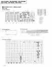

XR-P74OM.
XR-P64OM,
XR.P34OM
xR.-P7 4o-,
XR-P64HJ_,
XR-P340
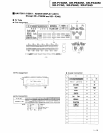
FM/AM TUNER MODULE
2.
POWER AMP
MODULE SECTTON
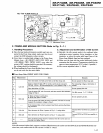
(Refer
to
Fig. 2-1.1
1.
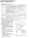
Handling Precautions
o
Since
the heat sink and transistor metallic
parts
are con-
nected to the Front Amp
output, make sure they do not
contact the
GND
(chassis)
or other circuits.
o
Since there is residual
high voltage in the Power Amp
Module Assy
+31
(FRONT
ASSY FOR 100W)
and
+B2
(REAR,
PWR, PRTEC ASSY)
even when the
power
is
OFF, caution should be
exercised.
(If
necessary,
the voltage should
be discharged).
a
When handling the Power Amp
Module Assy, make
sure
you
do not
touch the fan motor
blade.
I
Front Amp
Side
(FRONT
ASSY FOR 1OOW)
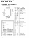
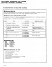
2. Adjustment
and Confirmation of ldle Current
o
Basically,
the idle crurent needs to be confirmed
when
replacing a
power
transistor,
driver transistor, or bias
transistor,
or when the entire split board Assy
of the
Power Amp
Module Assy has been replaced.
o
Make sure
the heat sink has cooled sufficiently
before
measuring
the idle current.
(Temperature
should
be the
same
as room temperature; 25oC is
ideal, if
possible.)
o
Idle
current stipulated value:
3-50mA.
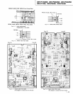
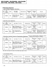
Fig. 1
-3
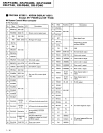
Adjustment Points
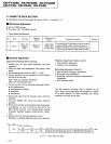
itep Measurement
Item
Remarks
I
Lch side
Short both sides of
C7L23 afi C7L24 on the Rear Amp
side. Do not operate the Rear
Amp side.
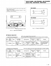
2
Insert a resistor
(0.220,
3W or more) in series
in the connector
CN7502 *81
(or
-81)
line
(terminal
No.
5 or 6).
(Refer
to FiS.2-2.\
For measuring
voltage
at both sides of
resistor
3
Short both sides of C7524.
Do not operate Rch
side.
Turn
the
power
ON, wait 6
seconds, and then measure
the resistance
voltage in
Step 2.
Lch Idle
current l:V/0.22
(0)
5
Rch side
o
Same as Steps
1 and 2 above.
.
Short both sides otC7523.
Do not
operate Lch side.
6
Turn the
power
ON under the above conditions,
and after 6 seconds
measure
the resistance voltage in
Step 2.
If the
measured idle current is
greater
than 50mA,
perform
the follow-
ing
procedure.
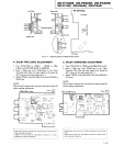
8 Lch
side Short between
the Point A
pattern
in Fig. 2-3
using solder.
Connect
R7517
to R7515 in a
parallel
cir-
cuit.
I
Rch side Short
between the Point B
pattern
in
Fig. 2-3 using solder.
Connect R7518
to R7516 in a oarallel cir-
cuit.
10
After
performing
Steps
8
and 9, remeasure
the idle current
and con-
firm
that it is below 50mA.
NOTE:
If
the idle current is
below 3mA, support
a resistor
(33kQ)
between the emitter and
the
Q7501
(Lch)
and
Q7502
(Rch)
bias tran-
sistor
base, and confirm that
the idle cunent is within
3-50mA.
1-21