


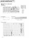

XR-e2461y1,
XR-P640M, XR-P34()M
)(R-P7
Q,
XR-P64O,
XR-P34O
!
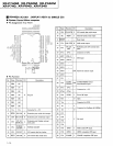
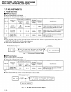
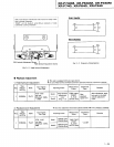
Rear Amp Side
(REAR,
PWR,
PRTEC ASSY)
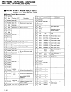
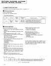
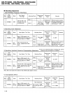
Step Measurement
Item Remarks
1
Center amp side
Short
both sides of C7523 and C7524 orr the Front Amp
side. Do
not
operate the Front
Amp
side.
2
Insert a resistor
(0.220.
2W or more) in series in the conDector
CN7102 +B2
(or
82)
line
(terminal
No. 5 or 6).
(Refer
to Fig. 2-4.)
For measuring voltage at both sides of
resistor
3 Short both sides of C7124 on the Surround Amo side. Do not operate the Surround Amp.
4
Turn
the
power
ON, wait 6 seconds, and then measurc the resistance
voltage in
Step
2.
Idle current: |
=
Y10.22
(O)
5
Surrould amp side
a
Same as Steps I and 2 above.
Short both sides of C7123 on Surround Amo side.
a
Do not opemte Surround
Amp.
6
Turn the
power
ON under the conditions in Steps I and 2, and alter 6
seconds measure the resistance
voltage
in Step
2.
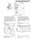
7
If the
measured idle current is
greater
than 50mA,
perform
the follow-
ing
procedure.
8
C€nter amp side
Short b€tween the Point
C
pattem
in Fig. 2 5 using solder.
Connecl R7l17
to
R7115
in a
parallel
cir
-
cult.
9
Surround amp side
Short between the Point D
pattern
in Fig.2 5 using solder.
Connect R7118 to R7116 in a
parallel
cir-
cuit.
10
AJter
performing
Steps 8 and 9, remeasure the idle current and con-
firm that it is below 50m-{.
NOTE:
If the idle current is below 3mA, support a resistor
(15kQ
)
between
the emitter and the
Q7101
(Center-ch)
and
Q7102
(Surround-
ch)
base.
and confirm that the idle current is
within
3-50mA.
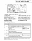
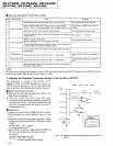
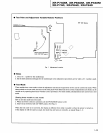
3. Adjusting the Operating
Temperature Setting
This adjustment is necessary
when IC7403
(+12V
regulator),
Q7301
and
Q7302
(temperature
sensors), or
VR7701 has been
replaced, or when the entire split board
Assy of the Power Amp
Module Assy has been replaced.
I
Adjustment-Related Cautions
a
Make
sure the heat sink has sufficiently cooled
(is
the
same as room temperature
Ta.)
a
Once the
power
has been turned ON, make
measurements and adjustments as
quickly
as
possible,
(If
too much time is taken, the
heat sink temperature will
rise, and the
measurements will deviate
from
the
Ta
measurement
point.)
I
Adiustment
1. Connect a
voltmeter between TEMP and TP
(or
between
IC7702 terminals
No.3 and 2).
(Refer
to Figs.
2
3
and
2-6.)
2. Determine the
fan motor operating temperature
setting
by means of the following
formula.
(Tolerance
is within
t30mV.)
Formula:
(85oC
-
Ta)
x
19
(mV)
Ta: ambient lemp€rature
("C)
3. Adjust VR7701 so that the
voltage between TEMP and
TP is the value obtained
from the above Iormula.
For examole:
when the room temperature
is 25oC,
set value
:
185
-
25)
x
19
{mV}
=
1140mV
{tolerance
within t3OmV).
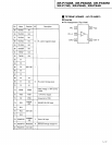
't
-22
of the
Fan Motor
(VR77O1l
FROIT ASSY FOR l OOW
FAN
+12V
R7708
R7749
R771 0
R771 1
VR7
Fig. 2-6 Adjustmenl of Opersting
Temperatur€ Setting
ot Fan
Motor
701
@