


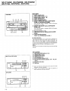
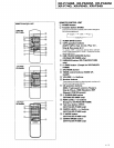
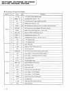


XR-P74OM, XR-P64OM,
XR-P34OM
xR-P7
N,
XR-P64(), XR-P34()
(FOR
EUROPEAN MODEL ONLY}
AVATTAESSA
JA
SUOJALUKITUS
OHITETTAESSA OL€T ALTTIINA
NAKYMATToMALLE
LASERSATEILYLLE
ALA KATSO SATEESEEN
USYNIIG LASEESTRALING VED ABNING
NAB SIKKERHEDSAFBRYDEFE
ER
UDE
AF
FUNKTION
UNDGA
UDSAETTELSE FoR
STFALING
OSYNLIG LASEASTRAINING NAB DENNA
D€L
AB
oPPNAo ocH SPABaEN
AB
URKOPPLAO
AETRAKTA EJ STRALEN
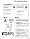
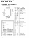
OEVICE INCLUOES LASER
OIODE
WHICH
EMITS INVISIBLE INFRABED BADIATION
WI]ICH IS
DANGEROUS
TO
EYES
THERE IS
A WARNING SIGN ACCOROING TO PICTURE
] INSIOE THE
DEVICE CLOSE
TO
THE LASER
DtooE.
THIS PIONEER APPANATUS
CONTAINS
LASER OF CLASS
].
SERVICING OPERATION OF
THE
APPARATUS
SI-IOULD BE DONE BY A SPECIALLY
INSTRUCTED
PERSON
MAXIMUM
OUTPUT
POWER:
5
mw
WAVELENGTH: 78O 785 nm
LABET
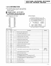
CHECK
tr<
Refer to
page
1
-29.
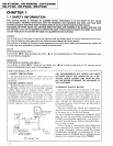
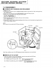
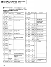
FOR
CD SINGLE
FOR CD MULTI
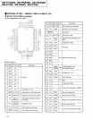
1. Laser Interlock Mechanism
Th6 ON/OFF
{ON
: low level, OFF : high lev€l)
status of 3601
(LPS1}
and S602
(LPS2)
switches for detecting rhe loading
stat€ is detected
by the systern microprocessor,
and the design
prevents
laser
diode
oscillation
except when borh switches
(LPS1
and LPS2I are ON
{low
level o. clampgd
state).
Thus, interlock will no longer
lunction it switches 360l
{LPSI)
and
S602
(LPS2)
are d€liberat€lv
shorted.
The int€rlock
also does not oDerat€ in
the t€st mode*.
Laser
diode oscillation will continue. if
pin
1 ot M51593FP
{lC101)
on the PRE-AMP
EOARD assembly loaded on
pickup
ass€mbly are
connected to GNO,
or
pin
19 is connected to low level
{ON),
or else
the terminal6
of O1O1 are shorted to each
other lfault condition).
2. When
the cover is opened
with the servo mechanism
block
remov€d
and turn€d
over, close viewing of the obj€ctive lens
with the nakod
eye will caus€
€xposure to a Class 1 laser beam.
CAUTION
[{vrsr8r,E rAsER
RA0tATtot{
wHHrl oPtN.
AVOIO
TXPOSUR€
T0
EEAM aRw1o23
CLASS 1
LASER
PRODUCT
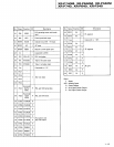
1.
Laser Interlock Mechanism
The
posilion
of the switch
(5601)for
detecting loading srare is
detecred by
the system microprocessor,
and the design
prevents
laser diode
oscillation when
the switch
(5601)
is not on CLMP
terminal side
{CLMP
signal is OFF or high
level,}.
Thus,
the interlock will no longer
function if rhe
switch
(5601)is
deliberately
set to CLMP terminal
side.
{low
level).
The interlock also
does not function in the
test mode*.
Laser
diode oscillation will continue,
if
pin
1 of M51593FP
(lC1O1)
on the PRE-AMP
BOARD ASSY mounted
on the
pickup
assembty
is
connected to
GND, or
pin
19 is connected
to
low
level
(ON),
or else
the terminals
of O1O1
are shorted to each other
lfault condition).
2. When the cover
is opened,
close
viewing
of the objective lens
with
the naked eve will
cause exoosure to
a Class
1
laser beam.
ARW1021
ARW
1 023
tr<
Refer to
page
1-29.
|
-J