


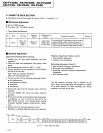


XR-P740M,
XR-P64()M,
XR-P340M
xR-P7
&,
XR-P64(),
XR-P34()
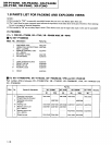
I
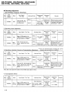
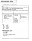
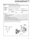
Focus
Offset Verilication
.
Objective
a
Symptom when out
of adjustment
Verify
the DC offset for the focus
error amp.
The
model does not focus in
and the RF sigaal is dirty.
a
Measurement
Instrument
Connections
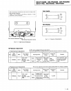
Connect the oscilloscope
to
TPl, Pin6
(FOER)
[Settings]
SmVldivision
l0ms7/division
DC mode
a
Player
State
a
Adjustment
Location
a
Disc
Test mode, stopped
(just
the
Power
switch on)
None
None needed
Pin6 FOER) is 0tsOmV.
IProcedurel
Verify the DC voltage
at TPl,
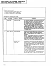
Note: If the specified values
cannot be obtained or no adjustment
is
possible
by
pertorming
the veifications
or adjustments
described in adjustment items 1-4, the
pickup
block may be defective.
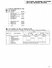
I
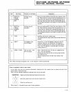
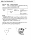
Tracking Error Balance Verification
.
Objective
a
Symptom
when
out
of adjustment
To verify
that there
is
no variation in the sensitivity of the tracking
photo
diode.
Play does not start or track search is impossible.
a
Measurement
Instrument
Connections
Connect the
oscilloscope to
TPl,
Pin2
(TRER).
This
connection may be Yia a low
pass
filter.
[Settings]
50mV7/division
5ms7/division
DC mode
a
Player
State
a
Adjustment Location
a
Disc
Test mode, focus and spindle
servos closed
and tracking
servo
open.
None
YEDS_7
Whon
thero is no
DC
componenr
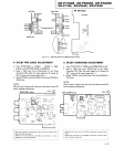
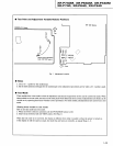
lProcedurel
1. Move
the
pickup
to midway
across the disc
(R:35mm)
with the MANUALz/TRACK SEARCH FWD
>>. >>l
key or REV
i{<1
.
<l{
key.
2. Press the DOLBY NR key, then
the
PLAY7/PAUSE
Futl
key in that order to close the focus servo then the spindle
serYo.
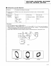
3. Line up the bright line
(ground)
at the center of the oscilloscope screen and
put
the oscilloscope into DC mode,
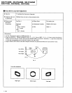
4. Supposing that the
positive
amplitude of the trackiqg error signal at TP1,
pin2
(TRER)
is
(A)
and the negatiye amplitude
is
(B).
the
following
expression is satisfied.
When
When
o=t,+']=o.r
A.B,
?']so.r
When lhsrg
is
a DC
compon€nt