10
CDX-M800
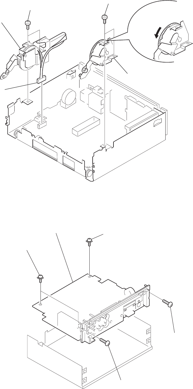
2-4. MOTOR BLOCK ASSY, CAM (R) ASSY
Note : Install the motor block assy and cam (R) assy in this roder.
For phase alignment between cams (L) and (R), see page 15 and 17.
2-5. MAIN BOARD
1
PTT 2.6x6
4
PTT 2.6x6
5
motor block assy
2
cam (R) assy
3
CNP902
A
Note: Install the cam (R) assy wit
h
the cam fully rotated in the
direction of the arrow
A
.
4
PTT 2.6x6
ground point
3
PTT 2.6x6
ground point
1
PTT 2.6x6
5
MAIN board
2
PTT 2.6x
6


