


19
CDX-M800
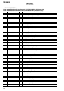
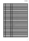
Pin No. Pin Name I/O Pin Description
51 DST SEL2 I Destination select signal input
52 CD LM LO O CD loading motor control signal output
53 CD LM EJ O CD eject motor control signal output
54 CD RST O CD servo reset signal output
55 CD AO O CD servo command/parameter discri. output
56 CD STB O CD servo data strobe signal output
57 CD TSTB O CD servo text strobe signal output
58 CD RFOK I CD servo RFOK signal input
59 CD XTALEN O CD servo crystal OSC control signal output
60 VCC2 — Power supply pin (+5V)
61 RESET OUT O Display CPU reset signal output
62 VSS — Ground
63 TEST IN I Test mode setting detect signal input
64 BUS ON O BUS ON control signal output
65 SYS RST O System reset signal output
66 BUS/AUX O BUS/AUX select control signal output
67 LINK OFF O Link OFF control signal output
68 ACC IN I Accessory key ON detect signal input
69 ILL IN I Ilumination line detect signal input
70 RC IN1 I Rotary commander signal input 1
71 NCO O Not used. (Open)
72 CD SELF SW I CD self SW detect signal input
73 TU ATT IN I Tuner mute control signal input
74 CLOSE SW I Front panel close detect signal input
75 OPEN SW I Front panel open detect signal input
76 I-DET I Front panel current detect signal input
77 MOT– O Front panel open/close control signal output
78 MOT+ O Front panel open/close control signal output
79 ROMC EN I ROM correction enable signal input
80 QUALITY I Tuner noise detect signal input
81 MPTH I Tuner multi-path signal input
82 VSM I S-meter signal input
83 SA IN I SA data input
84 KEY IN1 I Key signal input 1
85 KEY IN0 I Key signal input 0
86 RC IN0 I Rotary commander signal input 0
87 KEY ACK2 I Key acknowledge detect signal input 2
88 KEY ACK0 I Key acknowledge detect signal input 0
89 KEY ACK1 I Key acknowledge detect signal input 1
90 OPEN KEY I Open key detect signal input
91 RAM BU I RAM reset detect signal input
92 FLD ON O FL driver power supply ON/OFF signal output
93 FL ON O FL power supply ON/OFF signal
94 AVSS — Ground
95 DISP CE O Display CPU chip enable output
96 VREF — A/D converter reference voltage (+5V)
97 AVCC — Power supply pin (+5V)
98 DISP SI/RX I Display CPU BUS data input
99 DISP SO/TX O Display CPU BUS data output
100 DISP CKO O Display CPU BUS clock output