


5
TABLE OF CONTENTS
1. GENERAL
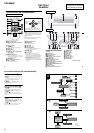
Location of Controls................................................................ 6
Connection example (US, Canadian Model)........................... 6
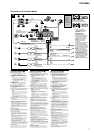
Connections (US, Canadian Model)........................................ 7
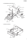
2. DISASSEMBLY
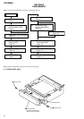
2-1. Front Panel Assy ................................................................. 8
2-2. CD Mechanism Block, Front Panel Assy............................ 9
2-3. Sub Panel (CD) Sub Assy ................................................... 9
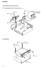
2-4. Motor Block Assy, Cam (R) Assy ..................................... 10
2-5. Main Board ....................................................................... 10
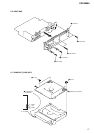
2-6. Heat Sink ........................................................................... 11
2-7. Chassis (T) Sub Assy ........................................................ 11
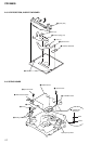
2-8. Lever Section, In Self SW Board ...................................... 12
2-9. Servo Board....................................................................... 12
2-10. Shaft Roller Assy, Load SW Board................................... 13
2-11. Floating Block Assy .......................................................... 13
2-12. Optical Pick-up Block ....................................................... 14
3. PHASE ALIGNMENT
3-1. Arm (A-L) Assy, Arm (B-L) Assy..................................... 15
3-2. Cam (L) ............................................................................. 15
3-3. Motor Block ...................................................................... 16
3-4. Alignment between Arm (A-L) Assy
and Arm (B-L) Assy .......................................................... 16
3-5. Arm (A-R) Assy, Arm (B-R) Assy .................................... 17
3-6. Cam (R) ............................................................................. 17
CDX-M800
4. DIAGRAMS
4-1. IC Pin Descriptions ........................................................... 18
4-2. Block Diagram –CD Section–........................................... 21
4-3. Block Diagram –Tuner Section– .......................................22
4-4. Block Diagram –Display Section–.................................... 23
4-5. Circuit Boards Location .................................................... 24
4-6. Schematic Diagram –CD Mechanism Section– ................ 25
4-7. Printed Wiring Boards –CD Mechanism Section–............ 26
4-8. Printed Wiring Boards –Main Section– ............................ 28
4-9. Schematic Diagram –Main Section (1/2)– ........................ 30
4-10. Schematic Diagram –Main Section (2/2)– ........................ 31
4-11. Printed Wiring Board –Sub Section– ................................ 32
4-12. Schematic Diagram –Sub Section– ................................... 33
4-13. Printed Wiring Board –Display Section– .......................... 34
4-14. Schematic Diagram –Display Section–............................. 35
4-15. IC Block Diagrams............................................................ 36
5. EXPLODED VIEWS
5-1. Chassis Section ................................................................. 39
5-2. Cam Section ...................................................................... 40
5-3. Main Board Section .......................................................... 41
5-4. Front Panel Section ...........................................................42
5-5. CD Mechanism Section (1) ............................................... 43
5-6. CD Mechanism Section (2) ............................................... 44
5-7. CD Mechanism Section (3) ............................................... 45
6. ELECTRICAL PARTS LIST......................................... 46