


SECTION 2. INSTALLATION
The hardware installation consists of plugging the cable into the PC and optional adapter, if
required, Com Port setup, and testing the Reader.
REQUIREMENTS
• Port Powered Swipe Reader
• Optional 9- to 25-pin Adapter, P/N 78200018
• PC with Com Port
• Procomm, Hyper Terminal, Mag-Tek Windows Drivers, or other RS-232 communications
program
MOUNTING
1. The Reader can be mounted on a surface in three ways:
• By two screws through the surface attached to the bottom of the unit and running the
cable on the top of the surface;
• By two screws through the surface attached to the bottom of the unit and by drilling a
hole in the surface for the cable and running the cable through the hole;
• By attaching the unit to the surface with fastening tape and running the cable on the top
of the surface.
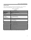
Note
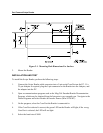
The two mounting inserts are 3 mm diameter; 0.5 mm pitch; 6.4
mm deep. The length of the screws used depends on the mounting
surface thickness and the thickness of washers (if used).
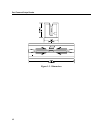
The mounting dimensions are shown in Figure 2-1. Determine the method of mounting
required.
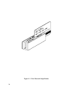
2. Ensure the Reader is positioned on a flat, accessible surface with at least 4 inches
clearance on either end for room to swipe a card. Orient the Reader so the side with the
LED is facing the direction of intended use.
If fastening tape is to be used, clean the area that the Reader will be mounted on with
isopropyl alcohol. Remove the adhesive protective cover on the fastening tape, and
position the Reader and push down firmly.