Performance Verification
4-20
2715 Spectrum Analyzer Service Manual
Performance requirement is
≥--15 dBm.
H Test equipment required:
2 Signal Generators
Combiner
3 SMA Male to BNC Female Adapters for Combiner
1. Recall default power up settings by pressing UTIL 1 1.
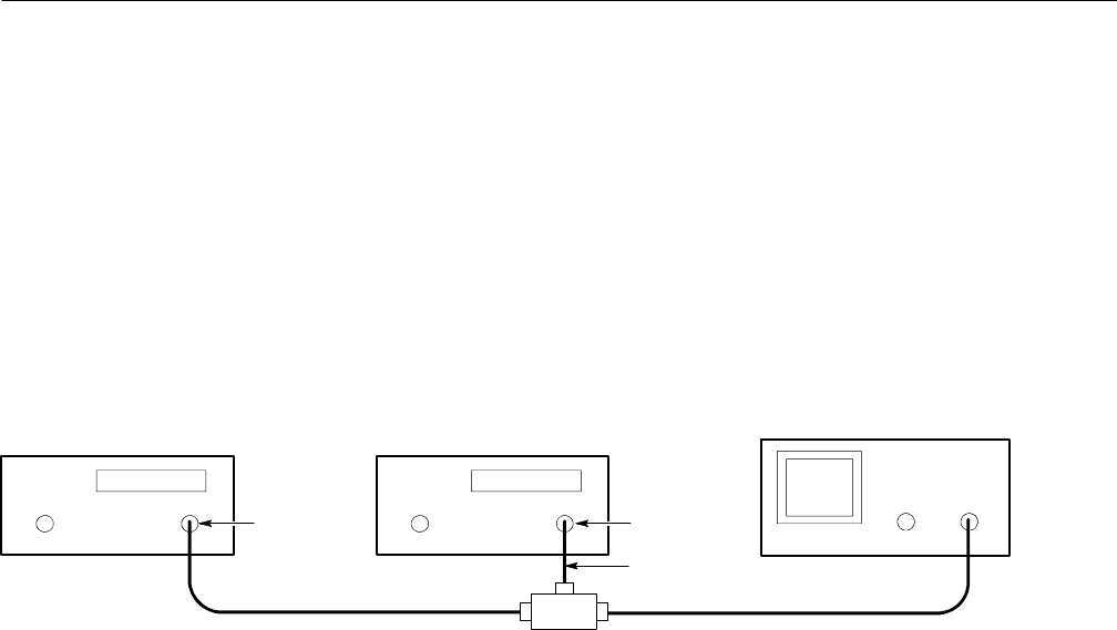
2. Connect the test equipment as shown in Figure 4 --3.
RF Output
Signal Generator Signal Generator
2715 Spectrum Analyzer
200 MHz
202.5 MHz
Directional Coupler
RF Output
*
Use min-loss pad for
75 Ω input
*
Figure 4- 3: 1 dB Compression Point Test Setup
3. Select the following settings on the Spectrum Analyzer:
FREQUENCY 200 MHz
REFERENCE LEVEL --30 dBm
SPAN/DIV 10 kHz
RESOLUTION BW 30 kHz
VID FLTR On
VERTICAL SCALE 1 dB/
4. Enable PEAK ACQUISITION mode by pressing DSPL 4.
5. Set one signal generator’s controls for a full screen, 200 MHz signal.
6. Set the second signal generator’s controls for a full screen, 202.5 MHz
signal.
7. Increase the output amplitude of the second signal generator until the
200 MHz signal on the CRT drops 1 dB.
8. Check that the second signal generator output is ≥--15 dBm.
9. Disconnect the test equipment from the RF INPUT.
1 dB Compression Point
