


INSTRUCTIONS
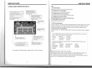
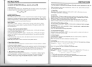
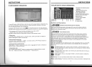
21.TROUBLE SHOOTING
PROBLEM
CAUSE
SOLUTION
Can not power on
Check whether power fuse
blew or not
Change fuse same as the old one
Some factor cause MPU wrong
Press RESET button
on
the panel by pen
operation point, then, power on
After ignition
switch off, setting
information all lose
Wrong connection between
ignition line ACC and
Constant
12
Volt wire
Change the wiring around
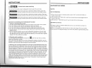
Remote control no
function
Noenoughpowersupp~
from battery
Change battery
in
remote control
Poor performance
of
radio station
Improper length of antenna,
poor connection of antenna
grounding
Check whether antenna
is
connected or not,
or poor connection
Can not load disc
The disc will not go
in
all
the way
Remove the 2 screws
on
top of the radio
Disc is scratched Change new disc
Can not play disc
Put wrong side of disc into unit
Slot
in
the disc with sign side up
Lens has dirty
Clean lens by lens clean disc
Can not switch
language/subtille
There
is
only one language/
subtitle
in
disc
If disc
is
not with
multi-Iangua~e
/
subtitle,
it
cannot switch language/subtit e
No image
Video line between unit and
TV
is
not properly connected
Reconnect lines
INSTRUCTIONS
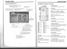
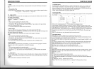
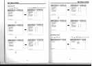
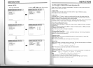
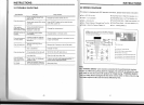
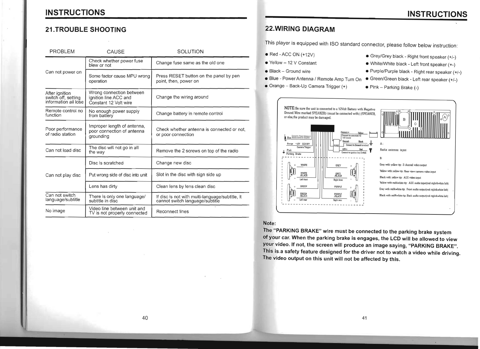
22.WIRING DIAGRAM
This player
is
equipped with ISO standard connector, please follow below instruction:
• Red - ACC ON (+12V)
• Grey/Grey black - Right front speaker
(+/_)
• Yellow - 12 V Constant
• WhitelWhite black - Left front speaker (+-)
• Black - Ground wire • Purple/Purple black - Right rear speaker (+
/_)
• Blue - Power Antenna / Remote Amp Turn On • Green/Green black - Left rear speaker (+/
_)
• Orange - Back-Up Camera Trigger (+) • Pink - Parking Brake
(_)
NOTE:s,
sure th,
un
il
is conn,cled
10
a 1
2Volt
Sallery
wllh
N,gaUvs
Ground
.
Wlre
marked
SPEAIlERI-]musl
be
conneOled
withl-]SPEAIIER,
or
el
Sl:,the
product
may
be
damaged.
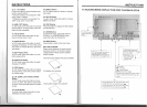
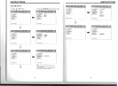
A:
Radio
antenna
InpUt
--:
~::J
~
Y,WIT
...
!BLACK
- leItfrcnt
~------
G~Y
~
GREY
11
!BLACK
..
flJgbtfront
-
B·
Gray
with
yellow
tip
: 2 c
banrie
l
Video
output
YeUaw
WIth
yellow
up
:
Re
ar
\1ew
camera
video
input
Black
\v1lh
yellow
up:
AID:
video
input
Yellow
wlIh
red&whl
te
tip
:
AID:
audlo
lnput(red
rlghl&while
l
elt)
G~EN
PllRP
LI'
Grey
with
re.d&whi
le
up:
F
ront
audkl
outpul(red
rlgbt&wnUe
left)
~
GRtEN
/BLAClI
PllRPLI'
IB
LAC
il
~
Black
'.'11th
I1ld&.whlls
Up
:
Back
audJo
outpur(red
rtghl&.whils
laft)
- - -
--
-
ll'
ft
~ar
- -
--
- - - - - - -
H1qhtl''n
r
,
- - - - - -
--
-- -
--
Note:
The "PARKING
BRAKE"
wire
must
be
connected
to
the
parking
brake
system
of
your
car. When
the
parking
brake
is
engages, the LCD
will
be
allowed
to
view
your
video.
If
not, the
screen
will
produce
an
image
saying, "PARKING
BRAKE".
This is.a safety feature
designed
for
the
driver
not
to
watch
a
video
while
driving.
The
video
output
on
this
unit
will
not
be affected by
this.
-
40
41