


CAMCO USER MANUAL
VORTEX POWER AMP SERIES
P.17
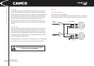
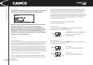
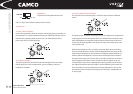
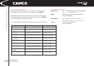
Left position:
Clip Limiter: OFF & Speaker Protect: OFF
(See 4.4.1,Clip Limiter and 4.4.3, Speaker Protect Limiter)
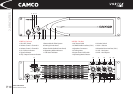
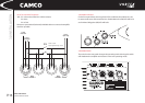
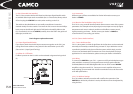
4.3 Indicators
4.3.1 On / Failure Indicators
Under normal operation, after the amp has started, the green power LEDs are
permanently lit. A variety of different sequences of ashing LEDs are used to
indicate other operating states and errors in one of the channels of the
power amp. (See 6.0, Trouble Shooting)
4.3.2 Signal Indicators
The green signal LED is illuminated when the voltage level at the output
reaches approx. 4 V; this corresponds to a power of approx. 4 W at an
impedance of 4 Ohms.
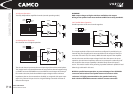
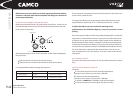
4.3.3 Clip / Output Current Indicators
The clip LED’s are bi-coloured: green / red. Each colour indicates a different
status.
The green section is subject to analogue control. The brightness is proportional
to the output current in the channel. The LED is visibly lit above around 1 Amp,
while full brightness corresponds to the maximum rated current. If the LED is
lit red only, no load is applied to the outputs or Clip is active with a duty cycle
of more than 10 %.
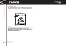
When under load, there is also a certain current that ows when controlling
the power level; the green section will be lit appropriately. If the power level is
taken to the limit, the green and red sections will appear mixed, resulting in a
shade of yellow that depends on the current. If the microprocessor detects a
clip signal with a duty cycle of more than 10 % within a time interval of 50 ms,
then it suppresses the green section so that the clip LED appears only red.
Careful analysis of the various dependencies when comparing channels that
are subject to identical control (possibly in several different power amps) will
allow conclusions to be drawn about the inherent impedances. This can aid
the detection of incorrectly wired components and faults in loudspeakers at
an early stage.
4.0 OPERATION
LIMITER
OFF
SpP
SpP Clip