


CAMCO USER MANUAL
VORTEX POWER AMP SERIES
P.22
NOTE: Ensure you return both pots to their original position after address
selection is complete, otherwise the amplier will change its volume level
to the new pot positions!
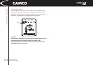
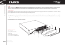
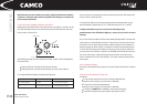
5.2.4 To Activate CAI Address Selection Procedure
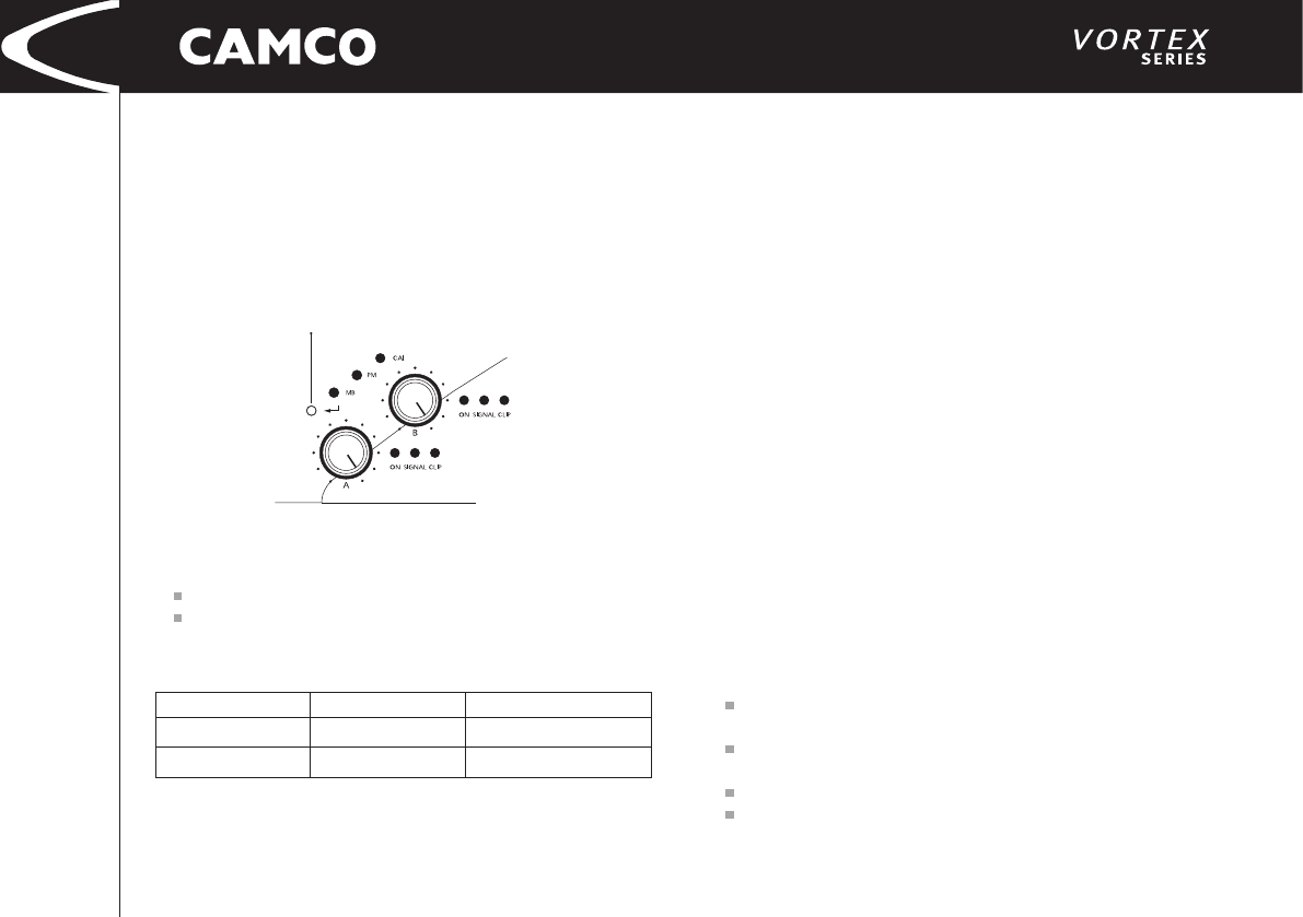
Briey press the ENTER -Switch. This push button switch (Enter - Switch) can be
accessed through the 3mm hole in the front panel located between the main
power switch and the LEDs.
After briey pressing the Enter-Switch the actual address will be displayed by
the power LEDs.
Flashing of Power LED channel A indicates the tens,
Flashing of Power LED channel B indicates the units of the address.
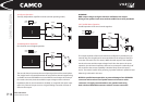
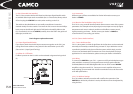
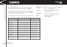
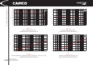
For example: different address setting LED sequences:
These sequences are repeated for 30 seconds (timeout). Then the Power LEDs
return to their normal function.
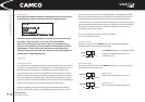
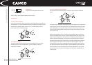
To change CAI address, turn the appropriate Volume Potentiometer to the
required address (Volume Pot Ch A => TENS, Volume Pot Ch B => UNITS).
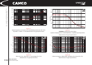
To adjust the address you can use the scale markings of the
potentiometers. You will nd the digits 0,1,2,3,4,5,6,7,8,9 on the 10 scale
spacing .
The current selected address will be immediately displayed BUT not automati-
cally stored or activated! After each turn of pot you have another 30 seconds
to timeout. You can leave this procedure without saving the new address by
briey pressing the Enter-Switch or waiting for timeout (as described above).
To store and activate the new address you have to press the Enter-Switch for
3 seconds. This new address is stored in an EEPROM, which holds the informa-
tion even if the amp is subsequently disconnected from mains. Be sure to
set the CAI-Master-PC to this new address. If not, the communication will be
interrupted.
5.2.5 CAI Status Indicator
This green LED indicates the presence of communication between PC and the
amp.
5.2.6 Overview Or Remote Controls CAI
CAI allows:
To control the output-level of each channel independently
(exception: mono modes, only channel A is affected)
To mute each channel independently
(exception: mono modes, only channel A is affected)
To switch the VORTEX into STANDBY mode (and back again)
To monitor temperature, output-signal, clip, output-current.
01 (factory settings)
25
Address
Power LED Channel B/ TENS
Power LED Channel A/ TENS
0* ash
2* ashes then short pause
1* ash then short pause
5* ashes then short pause
Enter Switch
5.0 OPTIONS