


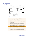
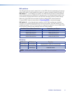
Dual Mode DisplayPort
The DP DA2 supports dual mode for interoperability with VGA, DVI, and HDMI display
devices. Appropriate adapters are required.
NOTES:
• Certain VGA displays that lack a scaler do not work properly with Dual Mode
DisplayPort.
• In some applications using DisplayPort adapters, the DP DA2 may be unable
to capture EDID of the display connected to output 1. Use SIS commands to
adjust the DDC speed (see page 15).
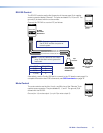
EDID Minder
During boot up, the source device uses the auxiliary channel to obtain
Extended Display Identification Data (EDID) from the display device.
This allows the output signal to match the resolution and refresh rate
of the display device.
EDID Minder allows the user to store and use EDID values for another
display device to ensure the output signal is compatible with both the
display devices.
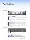
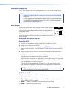
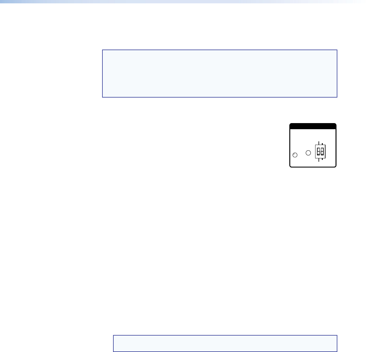
EDID Store push button and LED
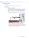
Recording EDID
1. Connect the display device that will provide EDID information to output 1.
2. Power on the display and the DP DA2.
3. Set DIP switch 1 in the Stored (down) position (see DIP Switches on the following
page for more information). The EDID Minder LED lights red until you start recording
EDID.
4. Press the EDID Store push button. The button is recessed (you may need a small
screw driver).
The EDID Minder LED lights amber while the EDID is being stored and turns green
when the recording process is successfully completed.
EDID information is read from the display device connected to output 1. The recorded
EDID is stored in non-volatile memory and is retained after a power cycle or after a
new display device is connected to output 1.
The new EDID is then available with DIP switch1 is in the Stored position. Each
time a new EDID is recorded, it overwrites the existing data and is available when
DIPswitch1 is in the Stored position.
NOTE: If the EDID for a display device is corrupted or cannot be read, the DP
DA2 will continue to use the currently stored EDID.
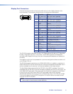
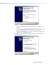
EDID Minder LED
The LED shows the status of the EDID recording process:
• Off — DIP switch 1 is set to Default.
• Red — DIP switch 1 is set to Stored, but external EDID has not been stored (the
factory default EDID is still present).
• Amber — New EDID information is currently being read and stored.
• Green — External EDID has been stored.
EDID
STORE
EXTEND
NORMAL
DEFAULT
STORED
EDID
DP DA2 • Panel Features 7