


Panel Features
This section describes the panel features and connections of the DP DA2.
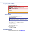
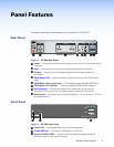
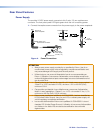
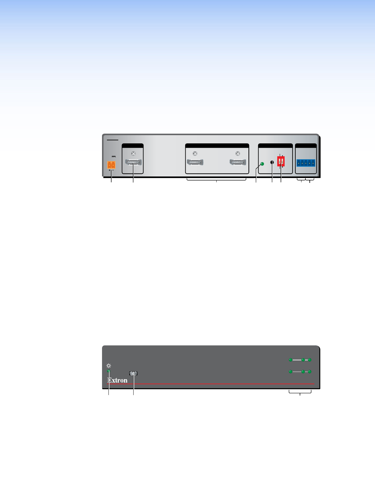
Rear Panel
12V
0.6A MAX
POWER
EDID
STORE
EXTEND
NORMAL
DEFAULT
STORED
1
RS-232 MUTE
RxTx 1G2
2
INPUT REMOTEEDIDOUTPUTS
DP DA2
AABBCCD
DE
EFFGGH
H
Figure 2. DP DA2 Rear Panel
A
Power — Connect the provided power supply to this 2-pole, 3.5 mm captive screw
connector.
B
Input — Connect the source device to this female DisplayPort connector.
C
Outputs — Connect up to two display devices to these female DisplayPort
connectors.
D
EDID Minder LED — Lights red, amber, or green, showing current EDID Minder
state.
E
EDID Minder Store push button — This recessed button activates EDID store.
F
EDID Minder DIP switches — Used to configure the EDID Minder features.
G
RS-232 control — Connect the transmit (Tx), receive (Rx), and ground (G)
connectors of this 5-pole, 3.5 mm captive screw connector to a control PC.
H
Mute control — Connect the ground (G) and either pin 1 (to mute output1) or pin 2
(to mute channel 2).
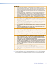
Front Panel
DP DA2
DISPLAYPORT DISTRIBUTION AMPLIFIER
CONFIG
AABBCC
INPUT
OUTPUTS
SIGNAL
HDCP
12
Figure 3. DP DA2 Front Panel
A
Power LED — Lights green when the unit is receiving power.
B
Config USB port — Connect this USB port to a control PC.
C
Signal and HDCP LEDs — Provide information about the signal and HDCP
encryption status of the input and outputs.
DP DA2 • Panel Features 3