Extron DTP HD DA4 4K 230/330 and DTP HD DA8 4K 230/330 • Installation and Operation 6
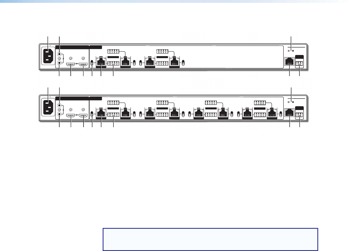
Rear Panel Features
50/60Hz
100-240V 1.0A
DTP HD DA4 330
LAN
3
4
1
2
DTP
HDBT
OUTPUTS
INPUT
HDMI
LOOP THRU
REMOTE
TxRx
RS-232
G
RESET
DTP
HDBT
OUT
SIG LINK
TxRx Tx RxG
RS-232 IR
TxRx Tx RxG
RS-232 IR
OVER TP
OUT
SIG LINK
DTP
HDBT
OUT
SIG LINK
TxRx Tx RxG
RS-232 IR
TxRx Tx RxG
RS-232 IR
OVER TP
OUT
SIG LINK
DTP
HDBT
DTP
HDBT
AUDIO
50/60Hz
100-240V 1.0A
DTP HD DA8 330
LAN
DTP
HDBT
OUT
SIG LINK
TxRx Tx RxG
RS-232 IR
TxRx Tx RxG
RS-232 IR
OVER TP
3
4
5
6
7
8
1
2
DTP
HDBT
OUT
SIG LINK
DTP
HDBT
OUTPUTS
INPUT
HDMI
LOOP THRU
REMOTE
TxRx
RS-232
G
RESET
DTP
HDBT
OUT
SIG LINK
TxRx Tx RxG
RS-232 IR
TxRx Tx RxG
RS-232 IR
OVER TP
OUT
SIG LINK
DTP
HDBT
DTP
HDBT
OUT
SIG LINK
TxRx Tx RxG
RS-232 IR
TxRx Tx RxG
RS-232 IR
OVER TP
OUT
SIG LINK
DTP
HDBT
OUT
SIG LINK
TxRx Tx RxG
RS-232 IR
TxRx Tx RxG
RS-232 IR
OVER TP
OUT
SIG LINK
DTP
HDBT
DTP
HDBT
AUDIO
A C I
B D E F G H J K
A C I
A
Power input — Connect the provided IEC connector to a 100-240 VAC (50 or 60 Hz)
power source.
B
Analog audio input — Connect an unbalanced stereo audio source to these 3.5 mm
mini stereo jacks.
NOTE: The units do NOT embed analog audio onto the HDMI signal. This analog
audio signal is transmitted simultaneously with audio embedded within the HDMI
signal.
C
Analog audio Loop‑Thru — Connect an audio system to this 3.5 mm mini stereo jack
for local loop-through monitoring of the source audio.
D
HDMI input — Connect a source device to this female HDMI type A connector (see
Connecting the Input Source on page 8 for more information).
E
HDMI Loop Thru — Connect a display to this female HDMI type A connector for local
loop-through monitoring of the source signal (see Connecting the Input Source on
page 8 for more information).
F
DTP/HDBaseT configuration switch — Set this 2-position, recessed switch
to configure the output between HDBaseT and DTP modes. When configured for
HDBaseT, use an HDBaseT-compatible receiver. When configured for DTP, use a
DTP-compatible receiver.
A
Power input
G
DTP/HDBaseT outputs
B
Analog audio input
H
Over TP RS‑232/IR connectors
C
Analog audio Loop Thru
I
Reset button and LED
D
HDMI input
J
LAN connector
E
HDMI Loop Thru
K
Remote RS‑232 connector
F
DTP/HDBaseT configuration switches


