


PS Engineering
PAV80 Series IFE System
Installation and Operator’s Manual
200-800-0101 Page 2-3 Rev 2 Sept. 2003
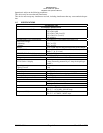
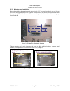
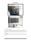
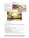
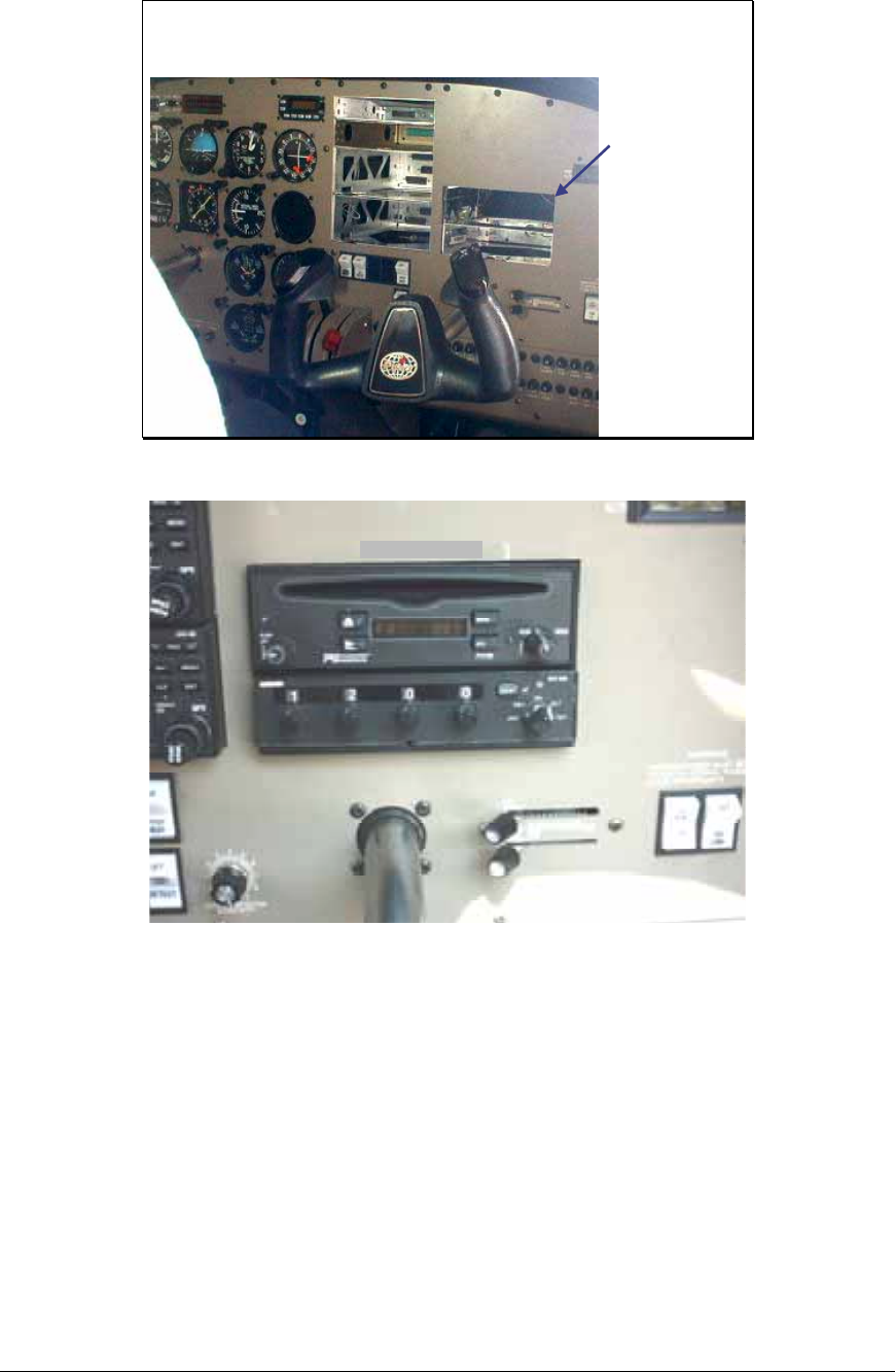
Panel Opening
Saw and
file used to
remove
existing
instrument
panel from
this
location
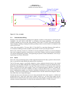
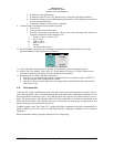
Figure 2-3 Completed panel opening (Typical)
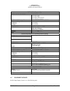
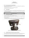
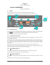
Figure 2-4 Completed panel installation
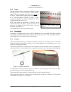
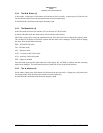
2.3.4 Connector Assembly
The unit connector mates directly with the circuit boards in the PAV80. The connector (part number 120-
425-4402 is a Molex crimp-type, and requires the use of a Molex hand crimp tool, EDP P/N 11-01-0203,
CR6115B (or equiv.). The connector is mounted to the unit tray with 2 ea. #4-40 screws, from the inside
of the tray.
After installing the connector, install the connector shield on the back of the tray with 2 ea #4-40 screws,
washers and nuts.
Ensure that proper strain relief and chafing precautions are made during wiring and installation of the tray
and shield.